Project 16 Read the Joystick
1. Description
The Joystick module is a component equipped with two analog inputs and one digital input. It is widely used in game controllers, robot control, and drone navigation.
The X and Y pins of the module are analog inputs, allowing you to directly read the measured analog values to determine direction and magnitude. The Z axis (B pin) acts as a digital button. To use it, you must first set its pin to the input state, and then read the value: 1 (pressed) or 0 (not pressed). In this project, we will read these values and print them to the serial monitor.
2. Component Introduction
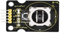
Joystick
The module primarily uses a PS2 joystick component. It contains three signal terminal pins that simulate a 3D space:
GND
VCC
Signal terminals: B, X, Y
X / Y (Analog):
X: Simulates movement along the X-axis.
Y: Simulates movement along the Y-axis.
When pushed in an arrow direction, the voltage value increases or decreases depending on the axis direction.
B (Digital):
Connected to a digital port.
Default output: 0
Pressed output: 1
Specifications:
Input Voltage: 3.3V ~ 5V
Output Signal: X/Y (Analog) + Z (Digital)
Applications: Plane coordinate control, servo control.
Features: Good tactile feedback, sensitive, and durable.
3. Wiring Diagram

4. Test Code
1. Preparations
Insert the Micro:bit mainboard into the robot arm’s 16-channel servo shield.
Connect the external power supply.
Connect the Micro:bit to your computer via a Micro USB cable.
Open the MakeCode editor (web or offline version).
2. drag the code manually
(Note: This project uses standard input/output blocks and does not strictly require the specific extension used in previous servo projects, but ensure your board settings are correct.)
3. Import Hex file
To import the Hex file directly, please locate the downloaded Hex file and drag it into the editor.
🏡Click to download the code for this lesson
After downloading the code, simply drag it directly into the coding area to upload it. (Note: The image below is for demonstration purposes only—please drag in the code you downloaded for this lesson above.)

5. Test Result
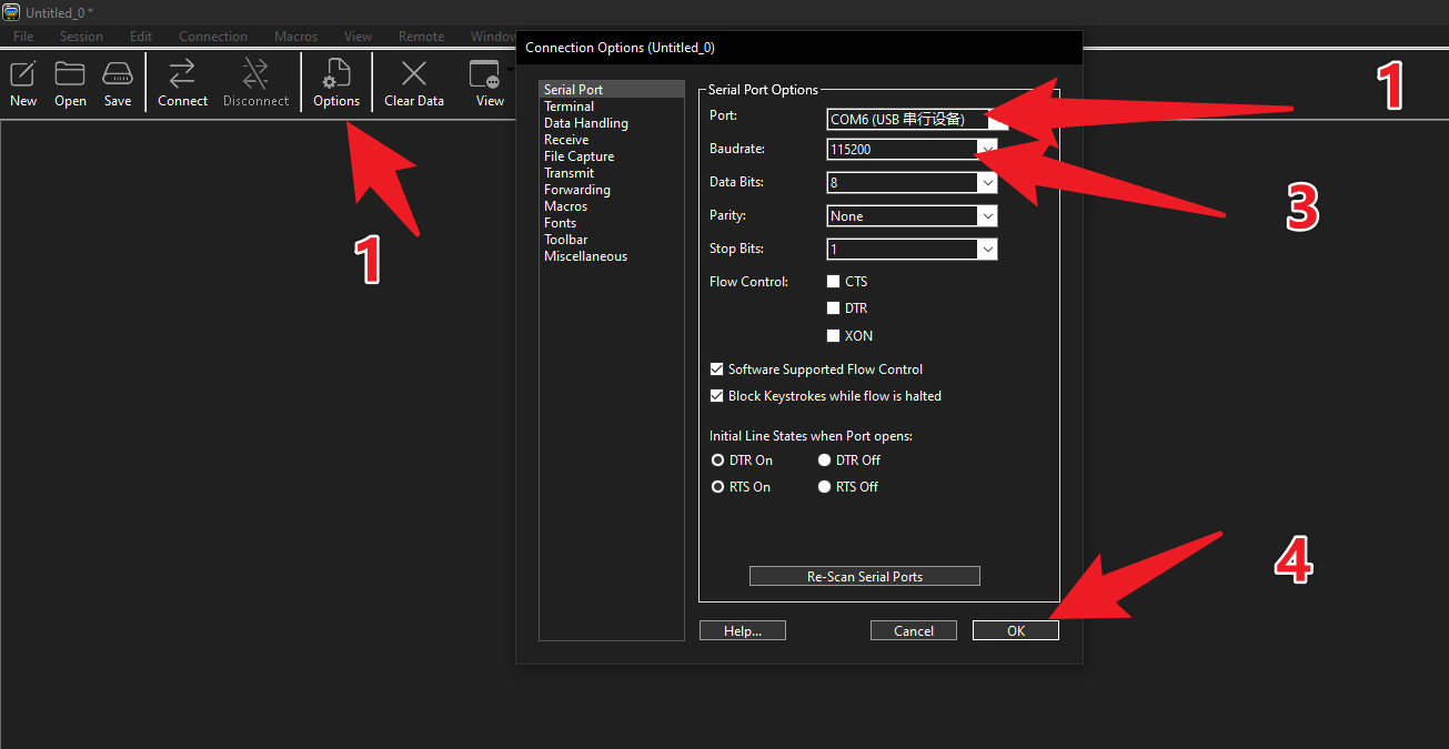
Open CoolTerm. As shown in the picture, select the Micro:bit’s COM port and set the Baud Rate to 115200. (Note: Please select the actual COM port number on your computer; it may not necessarily be COM6 as shown in the example image.)
The serial monitor will display the values in real-time:
Left joystick X analog value
Left joystick Y analog value
Right joystick Y analog value
Right joystick B digital value
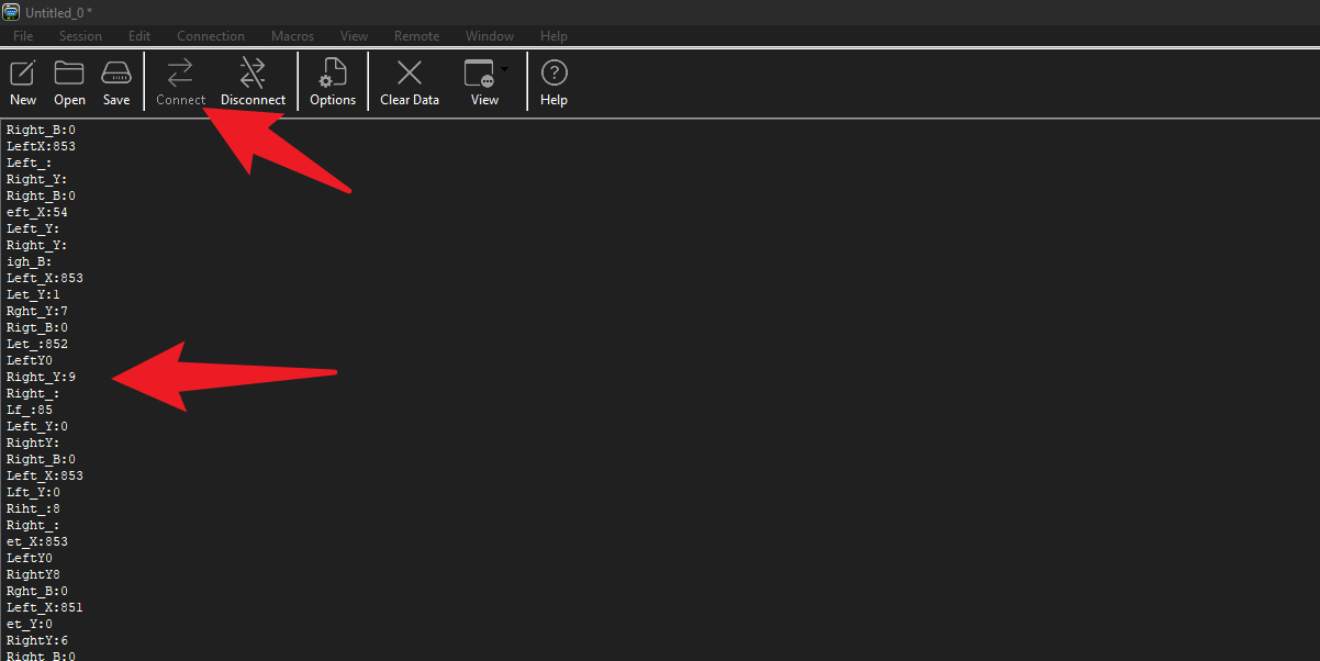
Shake the joystick or press the B button, and observe the values changing on the screen.