Project 19 BT Controls Robot Arm

1. Description
In this project, we will combine the BT APP and the BT on Micro:bit to realize multiple functions of the robot arm.
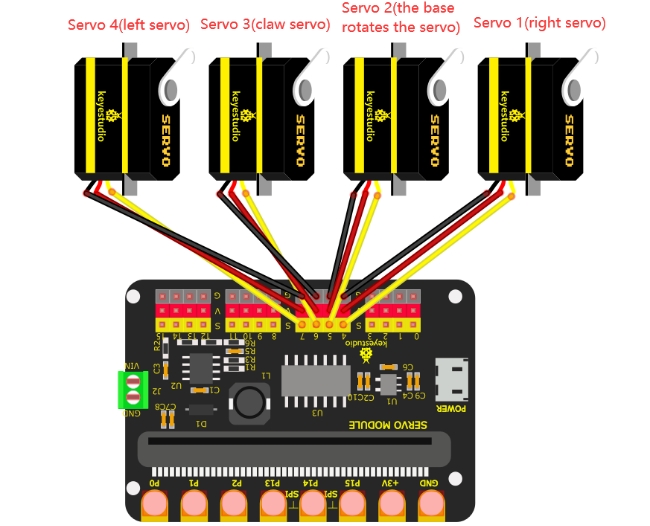
2. Wiring Diagram
Servo |
Function / Position |
Shield Port |
Brown Wire |
Red Wire |
Orange Wire |
|---|---|---|---|---|---|
Servo 1 |
Right |
Micro:bit 16-channel Servo Shield |
G |
V |
S(4) |
Servo 2 |
Base Rotation |
Micro:bit 16-channel Servo Shield |
G |
V |
S(5) |
Servo 3 |
Claw |
Micro:bit 16-channel Servo Shield |
G |
V |
S(6) |
Servo 4 |
Left |
Micro:bit 16-channel Servo Shield |
G |
V |
S(7) |
3. Preparations
Install the Micro:bit: Insert the Micro:bit mainboard into the robot arm’s 16-channel servo shield.
Note: Ensure the Micro:bit’s LED matrix is facing the correct direction (usually matching the silk screen markings on the shield).
Connect Power: Connect the external power source (battery pack or DC adapter) to the shield, and turn on the power switch on the shield.
Connect to PC: Connect the Micro:bit to your computer using a Micro USB data cable.
Check: You should see a drive named “MICROBIT” appear on your computer.
Launch Software: Open the MakeCode editor.
Web Version: Visit https://makecode.microbit.org/
Offline Version: Launch the MakeCode Offline App if installed.
drag the code manually (add the pca9685 extension library first).
Add the pca9685 Extension Library
Open Settings → Extensions.
Input the link:
https://github.com/keyestudio2019/pxt-pca9685-smallest
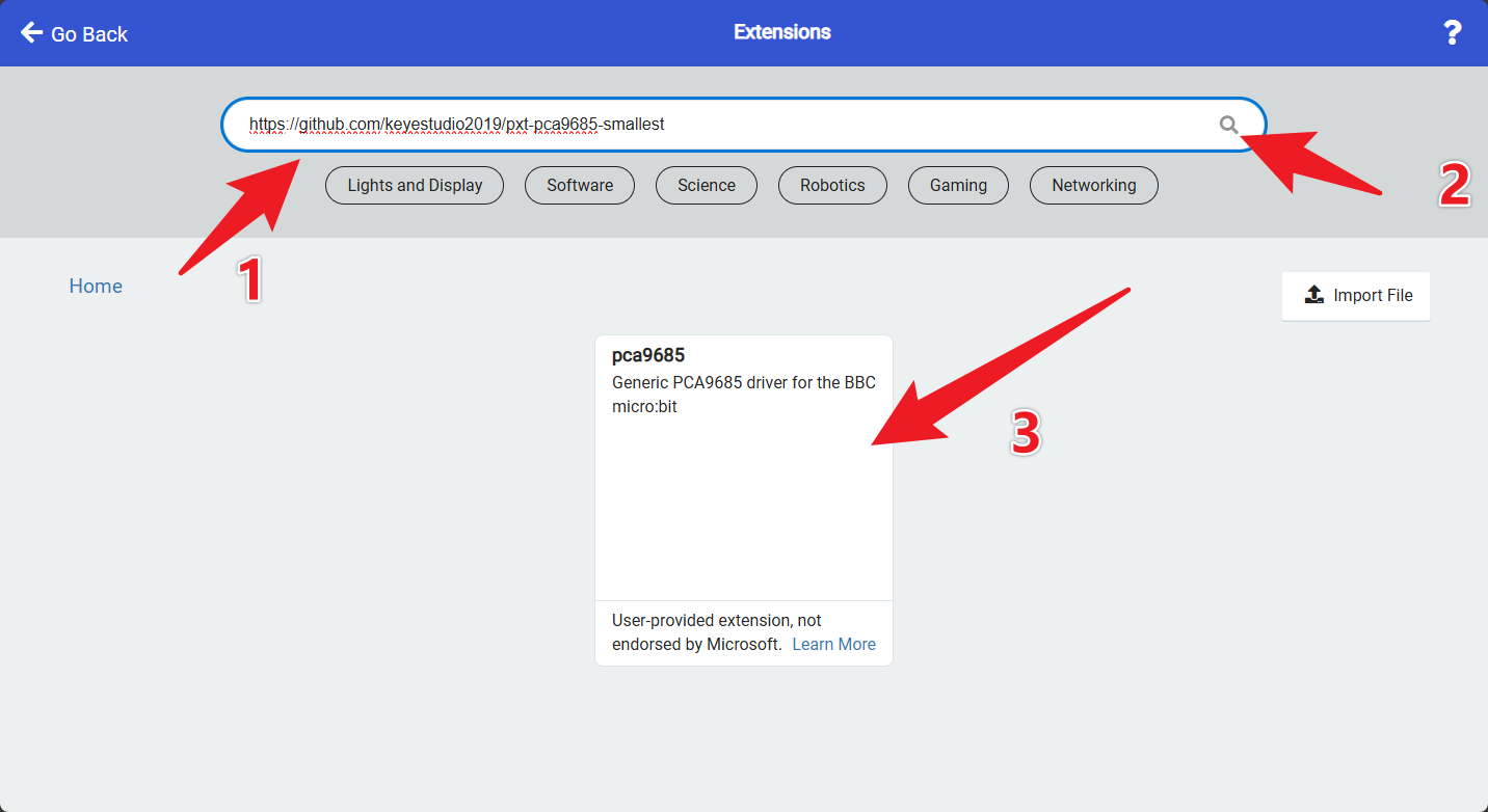
Search, download, and install the extension.
After installation, you’ll find the pca9685 extension library on the left.
4. Test Code
To import the Hex file directly, please locate the downloaded Hex file and drag it into the editor.
🏡Click to download the code for this lesson
After downloading the code, simply drag it directly into the coding area to upload it.
(Note: The image below is for demonstration purposes only—please drag in the code you downloaded for this lesson above.)

5. Test Result
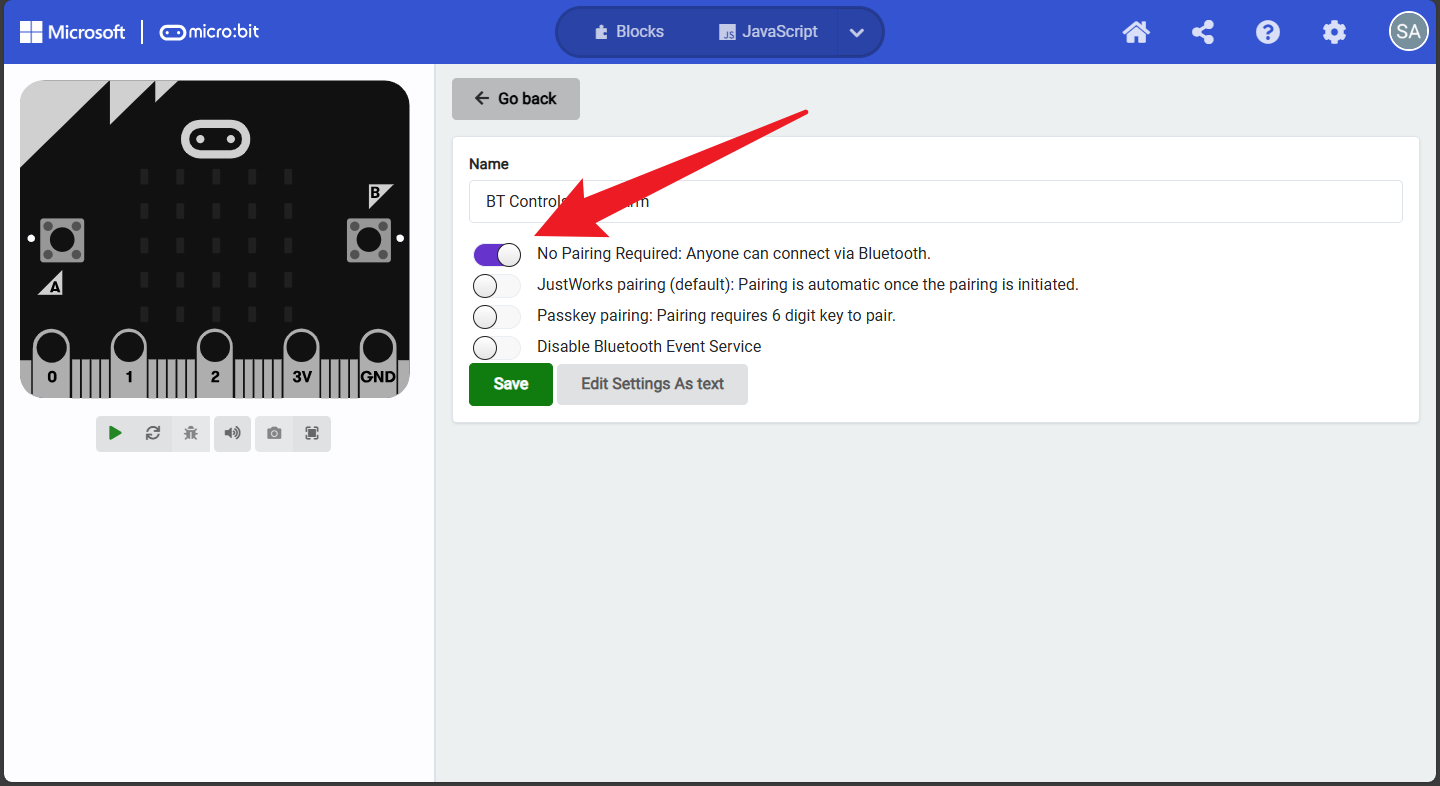
(1) Project Settings
Tap Settings → Project Settings, enter “BT Controls Robot Arm”, and set “No Pairing Required” to ON.
(Not required if importing the provided code directly.)
(2) Download & Connect
Download code to the Micro:bit mainboard and connect external power.
Open the “keyes arm” APP and connect via Bluetooth (refer to Project 18: Read BT Data).
Use the APP buttons to control the robot arm.
7.Functions of Buttons
|
Connect the APP to the Bluetooth of the microbit mainboard |
|
|---|---|---|
|
Disconnect the Bluetooth |
|
|
Press:“F”—>The big pendulum connected to servo 4 swings forward |
Release:“S”—->The big pendulum connected to servo 4 doesn’t move |
|
Press:“L”—>The robot claw will open |
Release:“S”—>The robot claw will not move |
|
Mode: 1 |
|
|
Press:“R”—>The robot claw will close |
Release:“S”—>The robot claw will not move |
|
Press:“B”—>The big pendulum connected to servo 4 swings backward |
Release:“S”—>The big pendulum connected to servo 4 doesn’t move |
|
Press:“f”—>The small pendulum connected to servo 1 swings backward |
Release:“S”—>The small pendulum connected to servo1 will not move |
|
Press:“l”—>Servo 2 turns left |
Release:“S”—>Servo 2 will not rotate |
|
Mode: 2 |
|
|
Press:“r”—>Servo 2 turns right |
Release:“S”—>Servo 2 will not rotate |
|
Press: “b”—>The small pendulum connected to servo 1 swings forward |
Release:“S”—>The small pendulum connected to servo 1 will not move |