Project 21: Servo Control
Overview
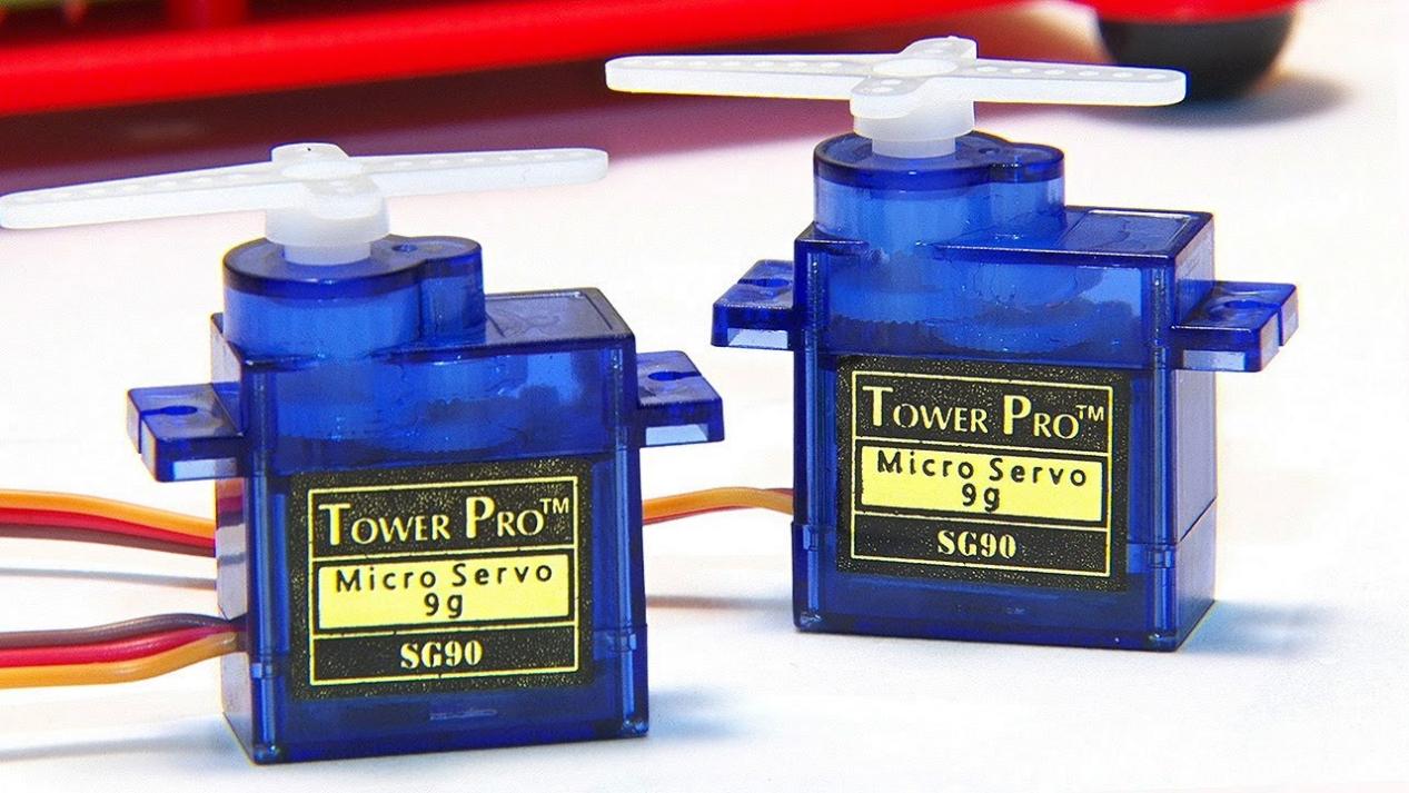
Servo is a position control rotary actuator. It mainly consists of a housing, a circuit board, a core-less motor, a gear and a position sensor.
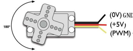
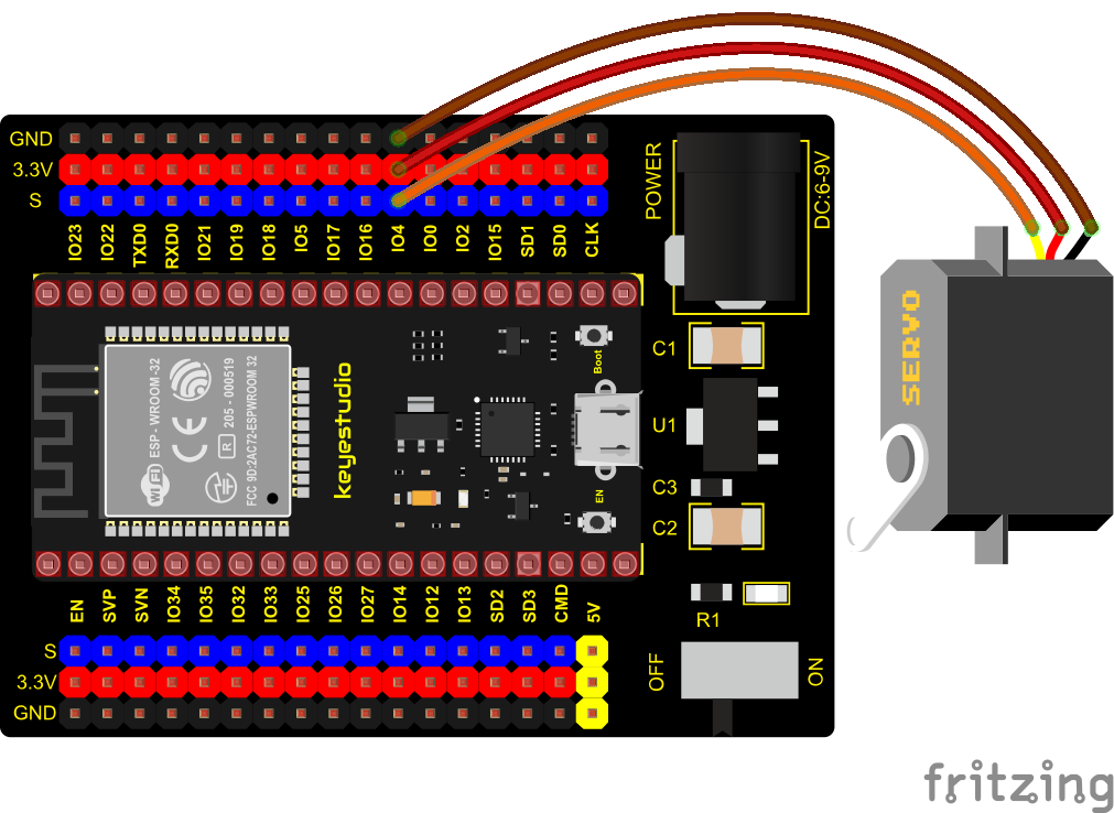
In general, servo has three lines in brown, red and orange. The brown wire is grounded, the red one is a positive pole line and the orange one is a signal line.
Working Principle
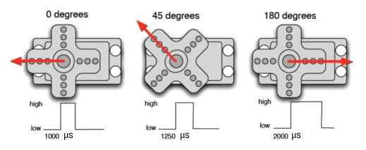
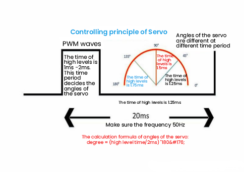
The rotation angle of servo motor is controlled by regulating the duty cycle of PWM (Pulse-Width Modulation) signal. The standard cycle of PWM signal is 20ms (50Hz). Theoretically, the width is distributed between 1ms-2ms, but in fact, it’s between 0.5ms-2.5ms. The width corresponds the rotation angle from 0° to 180°. But note that for different brand motors, the same signal may have different rotation angles.
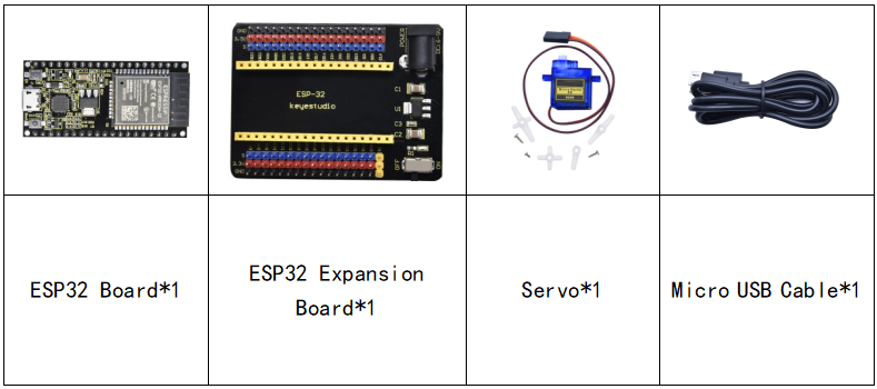
Components
Connection Diagram
Test Code 1
//**********************************************************************
/*
 * Filename    : Servo_1
 * Description : Steering gear rotation Angle 0-90-180, repeatly
 * Auther      : http//www.keyestudio.com
*/
int servoPin = 4;//steering gear PIN

void setup() {
  pinMode(servoPin, OUTPUT);//steering pin is set to output
}
void loop() {
  servopulse(servoPin, 0);//Rotate it to zero degrees
  delay(1000);//delay 1S
  servopulse(servoPin, 90);//Rotate it to 90 degrees
  delay(1000);
  servopulse(servoPin, 180);//Rotate it to 180 degrees
  delay(1000);
}

void servopulse(int pin, int myangle) { //Impulse function
  int pulsewidth = map(myangle, 0, 180, 500, 2500); //Map Angle to pulse width
  for (int i = 0; i < 10; i++) { //Output a few more pulses
    digitalWrite(pin, HIGH);//Set the steering gear interface level to high
    delayMicroseconds(pulsewidth);//The number of microseconds of delayed pulse width value
    digitalWrite(pin, LOW);//Lower the level of steering gear interface
    delay(20 - pulsewidth / 1000);
  }
}
//**********************************************************************
Code Explanation 1
1. map(value, fromLow, fromHigh, toLow, toHigh);Value is the value we map. fromLow, fromHigh is the maximum and minimum value;
toLow, toHigh are the upper limit and lower limit we map. For example, map(myangle, 0, 180, 500, 2500) means that an angle value myangle(0°-180°)the mapping range is from 500us to 2500us.
We use the function servopulse() to make the servo move. We also make the servo rotate 0°, 90°and 180°cyclically.
Test Result 1
Connect the wires according to the experimental wiring diagram, compile and upload the code to the ESP32. After uploading successfully,we will use a USB cable to power on, the servo will rotate 0°,90° and 180° cyclically.
Test Code 2
//**********************************************************************
/*
 * Filename    : Servo Sweep
 * Description : Control the servo motor for sweeping
 * Auther      : http//www.keyestudio.com
*/
#include <ESP32Servo.h>

Servo myservo;  // create servo object to control a servo

int posVal = 0;    // variable to store the servo position
int servoPin = 4; // Servo motor pin

void setup() {
  myservo.setPeriodHertz(50);           // standard 50 hz servo
  myservo.attach(servoPin, 500, 2500);  // attaches the servo on servoPin to the servo object
}
void loop() {

  for (posVal = 0; posVal <= 180; posVal += 1) { // goes from 0 degrees to 180 degrees
    // in steps of 1 degree
    myservo.write(posVal);       // tell servo to go to position in variable 'pos'
    delay(15);                   // waits 15ms for the servo to reach the position
  }
  for (posVal = 180; posVal >= 0; posVal -= 1) { // goes from 180 degrees to 0 degrees
    myservo.write(posVal);       // tell servo to go to position in variable 'pos'
    delay(15);                   // waits 15ms for the servo to reach the position
  }
}
//********************************************************************************
Code Explanation 2
myservo. write (pos) is the rotation angle to POS. myservo. read () reads the current angle value of the servo.
Test Result 2
Connect the wires according to the experimental wiring diagram, compile and upload the code to the ESP32. After uploading successfully,we will use a USB cable to power on, the servo will rotate from 0° to 180° by moving 1° for each 15ms.