Project 33: Ultrasonic Radar

Description
We know that bats use echoes to determine the direction and the location of their preys. In real life, sonar is used to detect sounds in the water. Since the attenuation rate of electromagnetic waves in water is very high, it cannot be used to detect signals, however, the attenuation rate of sound waves in the water is much smaller, so sound waves are most commonly used underwater for observation and measurement.
In this experiment, we will use a speaker module, an RGB module and a 4-digit tube display to make a device for detection through ultrasonic.
Required Components
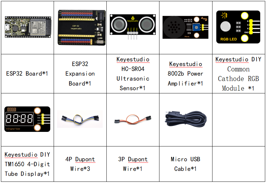
Connection Diagram

Test Code
//**********************************************************************************
/*
 * Filename    : Ultrasonic radar
 * Description : Ultrasonic control four digit tube, buzzer and RGB analog ultrasonic radar.
 * Auther      : http//www.keyestudio.com
*/
#include "TM1650.h" //Import the TM1650 library file
//the interfaces are GPIO21 and GPIO22
#define DIO 21
#define CLK 22
TM1650 DigitalTube(CLK,DIO);

int beeppin = 18; //Define the horn pin as GPIO18

int TrigPin = 13; //Set the Trig pin to GPIO13
int EchoPin = 14; //Set the Echo pin to GPIO14
int distance;//Distance measured by ultrasound

int ledPins[] = {0, 2, 15};    //define red, green, blue led pins
const byte chns[] = {0, 1, 2};        //define the pwm channels

float checkdistance() { //get distance
  // A short low level is given beforehand to ensure a clean high pulse:
  digitalWrite(TrigPin, LOW);
  delayMicroseconds(2);
  // The sensor is triggered by a high pulse of 10 microseconds or more
  digitalWrite(TrigPin, HIGH);
  delayMicroseconds(10);
  digitalWrite(TrigPin, LOW);
  // Read the signal from the sensor: a high level pulse,
  //Its duration is the time (in microseconds) from sending the ping command to receiving the echo from the object。
  float distance = pulseIn(EchoPin, HIGH) / 58.00;  //Convert to distance
  delay(10);
  return distance;
}

void setup() {
  DigitalTube.setBrightness();  //set brightness, 0---7, default : 2
  DigitalTube.displayOnOFF();   //display on or off, 0=display off, 1=display on, default : 1
  for(char b=1;b<5;b++){
    DigitalTube.clearBit(b);      //DigitalTube.clearBit(0 to 3); Clear bit display.
  }
  // DigitalTube.displayDot(1,true); //Bit0 display dot. Use before displayBit().
  DigitalTube.displayBit(1,0);    //DigitalTube.Display(bit,number); bit=0---3  number=0---9
  pinMode(TrigPin, OUTPUT);//Sets the Trig pin as output
  pinMode(EchoPin, INPUT);  //Set the Echo pin as input
  ledcSetup(3, 1000, 8);//setup the pwm channels,1KHz,8bit
  ledcAttachPin(18, 3);
  for (int i = 0; i < 3; i++) {   //setup the pwm channels,1KHz,8bit
    ledcSetup(chns[i], 1000, 8);
    ledcAttachPin(ledPins[i], chns[i]);
  }
}

void loop() {
  distance = checkdistance(); //Ultrasonic ranging
  displayFloatNum(distance);  //Nixie tube shows distance
  if (distance <= 10) {
    ledcWrite(3, 100);
    delay(100);
    ledcWrite(3, 0);
    ledcWrite(chns[0], 255); //Common cathode LED, high level to turn on the led.
    ledcWrite(chns[1], 0);
    ledcWrite(chns[2], 0);

  } else if (distance > 10 && distance <= 20) {
    ledcWrite(3, 200);
    delay(200);
    ledcWrite(3, 150);
    ledcWrite(chns[0], 0);
    ledcWrite(chns[1], 255);
    ledcWrite(chns[2], 0);
  } else {
    ledcWrite(3, 0);
    ledcWrite(chns[0], 0);
    ledcWrite(chns[1], 0);
    ledcWrite(chns[2], 255);
  }
}

void displayFloatNum(float distance){
  if(distance > 9999)
    return;
  int dat = distance*10;
   //DigitalTube.displayDot(2,true); //Bit0 display dot. Use before displayBit().
  if(dat/10000 != 0){
    DigitalTube.displayBit(1, dat%100000/10000);
    DigitalTube.displayBit(2, dat%10000/1000);
    DigitalTube.displayBit(3, dat%1000/100);
    DigitalTube.displayBit(4, dat%100/10);
    return;
  }
  if(dat%10000/1000 != 0){
    DigitalTube.clearBit(1);
    DigitalTube.displayBit(2, dat%10000/1000);
    DigitalTube.displayBit(3, dat%1000/100);
    DigitalTube.displayBit(4, dat%100/10);
    return;
  }
  if(dat%1000/100 != 0){
  DigitalTube.clearBit(1);
  DigitalTube.clearBit(2);
  DigitalTube.displayBit(3, dat%1000/100);
  DigitalTube.displayBit(4, dat%100/10);
  return;
}
  DigitalTube.clearBit(1);
  DigitalTube.clearBit(2);
  DigitalTube.clearBit(3);
  DigitalTube.displayBit(4, dat%100/10);
}
//**********************************************************************************
Code Explanation
We set sound frequency and light color by adjusting different distance range.
We can adjust the distance range in the code.
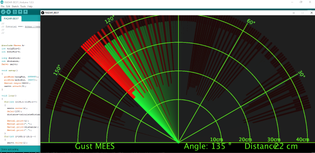
Test Result
Connect the wires according to the experimental wiring diagram, compile and upload the code to the ESP32. After uploading successfully,we will use a USB cable to power on. When the ultrasonic sensor detects different distances, the buzzer will produce different frequencies of sound, the RGB will show different colors, and the measured distances are displayed on the 4-digit tube display.