Project 7: Obstacle Avoidance Sensor
Overview
In this kit, there is a Keyestudio obstacle avoidance sensor, which mainly uses an infrared emitting and a receiving tube. In the experiment, we will determine whether there is an obstacle by reading the high and low level of the S terminal on the sensor.
Working Principle
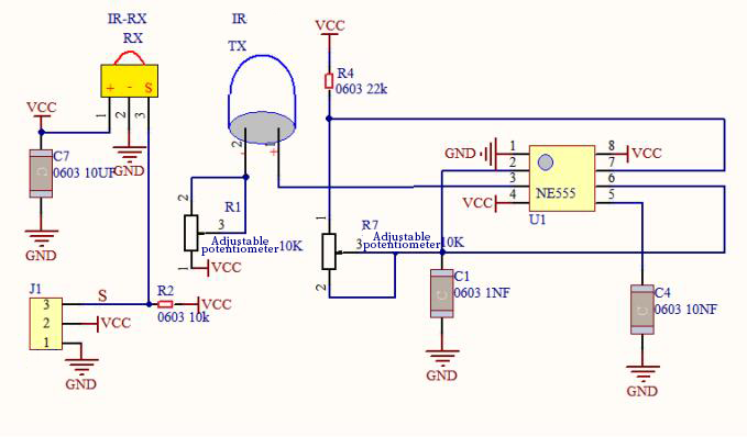
NE555 circuit provides IR signals with frequency to the emitter TX, then the IR signals will fade with the increase of transmission distance. If encountering the obstacle, it will be reflected back.
When the receiver RX meets the weak signals reflected back, the receiving pin will output high levels, which indicates the obstacle is far away. On the contrary, it the reflected signals are stronger, low levels will be output, which represents the obstacle is close. There are two potentiometers on the module, and one is for adjusting emission power, another one is for receiving frequency.
Components
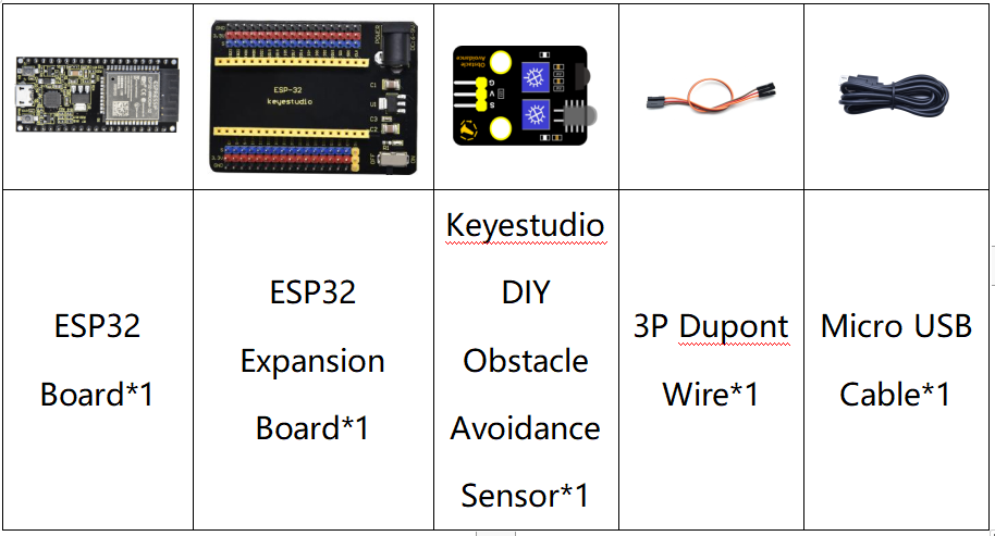
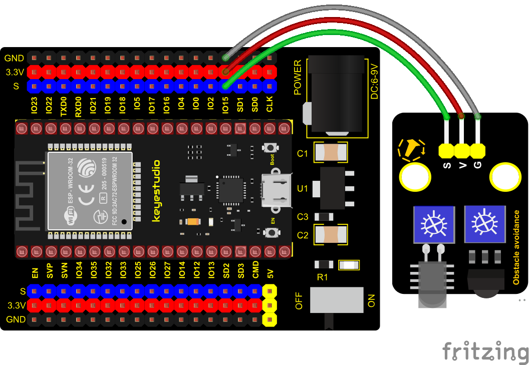
Connection Diagram
Test Code
//*************************************************************************************
/*
 * Filename    : obstacle avoidance sensor
 * Description : Reading the obstacle avoidance value
 * Auther      : http://www.keyestudio.com
*/
int val = 0;
void setup() {
  Serial.begin(9600);//Set baud rate to 9600
  pinMode(15, INPUT);//Set pin GP15 to input mode
}

void loop() {
  val = digitalRead(15);//Read digital level
  Serial.print(val);//Print the level signal read
  if (val == 0) {//Obstruction detected
    Serial.print("        ");
    Serial.println("There are obstacles");
    delay(100);
  }
  else {//No obstructions detected
    Serial.print("        ");
    Serial.println("All going well");
    delay(100);
  }
}
//*************************************************************************************
Code Explanation
Note:
Upload the test code and wire up according to the connection diagram. After powering on, we start to adjust the two potentiometers to sense distance.
Adjust the potentiometer transmitting power. Make the P LED at the critical point of ON and OFF states.
Adjust the potentiometer receiving frequency. Rotate it clockwisely, the frequency will increase. Make the S LED at the critical point of ON and OFF states, then the 38KHz square wave can be produced.
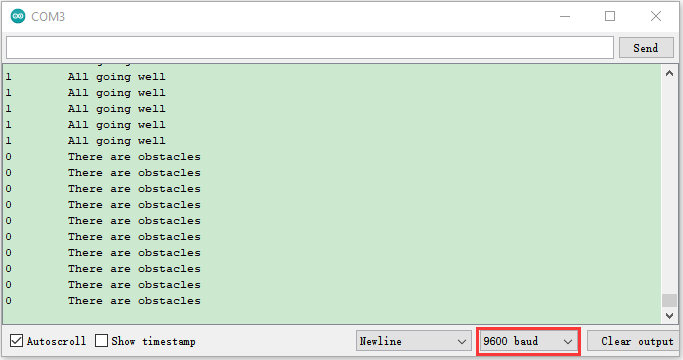
Test Result
Connect the wires according to the experimental wiring diagram, compile and upload the code to the ESP32. After uploading successfully,we will use a USB cable to power on,open the serial monitor and set the baud rate to 9600. The serial monitor will display the corresponding data and characters. When the sensor detects the obstacle, the val is 0, the monitor will show“There are obstacles”; if the obstacle is not detected, the val is 1,“All going well” will be shown.