Project 35: Bluetooth
This chapter mainly introduces how to use the bluetooth of ESP32 for simple data transmission with mobile phone. Experiment 35.1 is conventional bluetooth, and experiment 35.2 is bluetooth control LED.
Project 35.1:Classic Bluetooth
Components
|
|
|---|---|
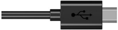
Micro USB Cable*1 |
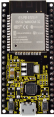
ESP32*1 |
In this project, we need to use a bluetooth dobbed serial bluetooth terminal for a study. If you haven’t install it, please click the installation: https://www.appsapk.com/serial-bluetooth-terminal/ .
Here is its sign
Component Knowledge
Bluetooth is a short-distance communication system that can be divided into two types, namely low power bluetooth (BLE) and classic bluetooth. There are two modes for simple data transfer: master mode and slave mode.
Master Mode: In this mode, work is done on the master device and can be connected to the slave device. When the device initiates a connection request in the main mode, information such as the address and pairing password of other bluetooth devices are required. Once paired, you can connect directly to them.
Slave Mode: A bluetooth module in the slave mode can only accept connection requests from the host, but cannot initiate connection requests. After being connected to a host device, it can send and receive data through the host device. Bluetooth devices can interact with each other, when they interact, the bluetooth device in the main mode searches for nearby devices. While a connection is established, they can exchange data. For example, when a mobile phone exchanges data with ESP32, the mobile phone is usually in master mode and the ESP32 is in slave mode.
master mode slave mode
Wiring Diagram
We can use a USB cable to connect ESP32 mainboard to the USB port on a computer.


Test Code
//**********************************************************************************
/*
 * Filename    : Classic Bluetooth--SerialToSerialBT
 * Description : ESP32 communicates with the phone by bluetooth and print phone's data via a serial port
 * Auther      : http//www.keyestudio.com
*/
#include "BluetoothSerial.h"

BluetoothSerial SerialBT;
String buffer;
void setup() {
  Serial.begin(115200);
  SerialBT.begin("ESP32test"); //Bluetooth device name
  Serial.println("\nThe device started, now you can pair it with bluetooth!");
}

void loop() {
  if (Serial.available()) {
    SerialBT.write(Serial.read());
  }
  if (SerialBT.available()) {
    Serial.write(SerialBT.read());
  }
  delay(20);
}
//**********************************************************************************
Test Result
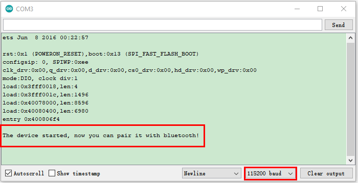
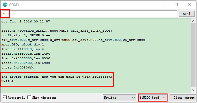
Compile and upload the code to the ESP32. After uploading successfully,we will use a USB cable to power on. Open the serial monitor and set the baud rate to 115200. When you see the serial prints the character, as shown below, it means that the ESP32’s bluetooth is waiting for connect ion with a phone. (If open the serial monitor and set the baud rate to 115200, the information is not displayed, please press the RESET button of the ESP32)

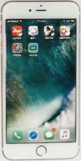
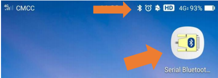
Ensure that your mobile phone bluetooth is enabled and the bluetooth application of “Serial Bluetooth Terminal” is installed.
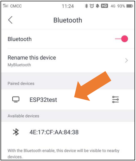
Click“Search”,search for the nearby bluetooth and select to connect the“ESP32 test”.
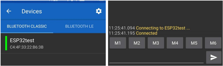
Open the software APP and click the left side of the terminal, select “Devices”.

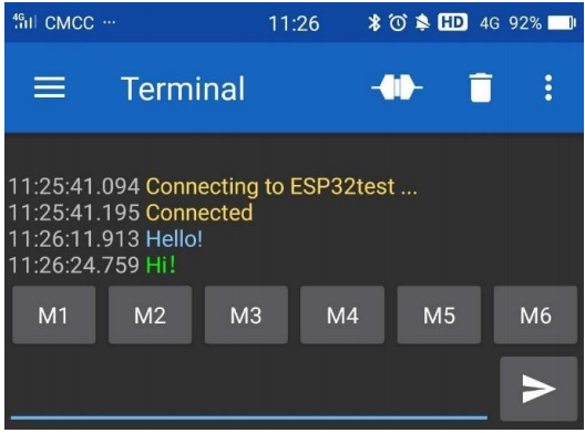
If you select ESP32test in classic bluetooth mode, a successful connection message will appear as shown below.
Data can be transferred between your phone and a computer via ESP32 now.
Send “Hello!”, When the computer receives it, which will reply with “Hi!”.
Project 35.2:Bluetooth Control LED
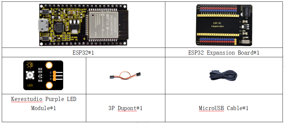
Components
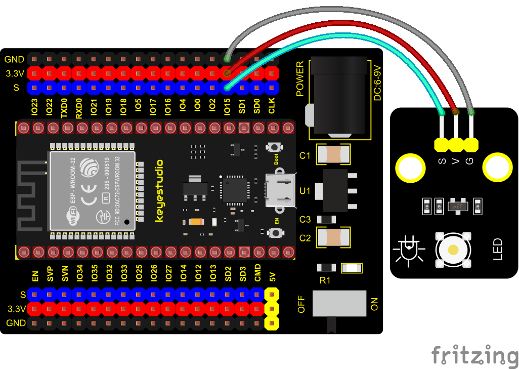
Wiring Diagram
Test Code
//**********************************************************************************
/*
 * Filename    : Bluetooth Control LED
 * Description : The phone controls esp32's led via bluetooth.
                When the phone sends "LED_on," ESP32's LED lights turn on.
                When the phone sends "LED_off," ESP32's LED lights turn off.
 * Auther      : http//www.keyestudio.com
*/
#include "BluetoothSerial.h"
#include "string.h"
#define LED 15
BluetoothSerial SerialBT;
char buffer[20];
static int count = 0;
void setup() {
  pinMode(LED, OUTPUT);
  SerialBT.begin("ESP32test"); //Bluetooth device name
  Serial.begin(115200);
  Serial.println("\nThe device started, now you can pair it with bluetooth!");
}

void loop() {
  while(SerialBT.available())
  {
    buffer[count] = SerialBT.read();
    count++;
  }
  if(count>0){
    Serial.print(buffer);
    if(strncmp(buffer,"led_on",6)==0){
      digitalWrite(LED,HIGH);
    }
    if(strncmp(buffer,"led_off",7)==0){
      digitalWrite(LED,LOW);
    }
    count=0;
    memset(buffer,0,20);
  }
}
//**********************************************************************************
Test Result
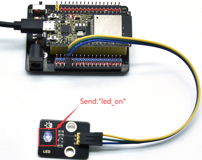
Connect the wires according to the experimental wiring diagram, compile and upload the code to the ESP32. After uploading successfully,we will use a USB cable to power on. The APP operation is the same as the project 35.1. To make the external LED on and off, simply change the sending content to “led_on” and “led_off”. Moving the APP to send data:
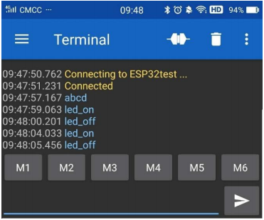
The serial monitor will display as follows:

LED Circumstance
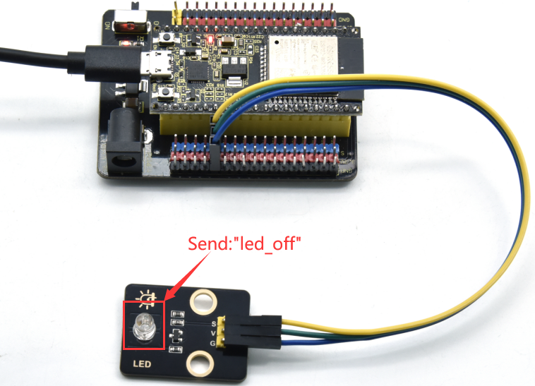
Note: If the sent content is not “led-on ‘or” led-off “, the status of the LED will not change. If the LED is on, it remains on when irrelevant content is received; Conversely, if the LED is off, it continues to be off when irrelevant content is received.