Project 27: Button-controlled LED

Overview
In this lesson, we will make an extension experiment with a button and an LED. When the button is pressed and low levels are output, the LED will light up; when the button is released, the LED will go off. Then we can control a module with another module.
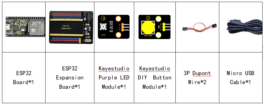
Components
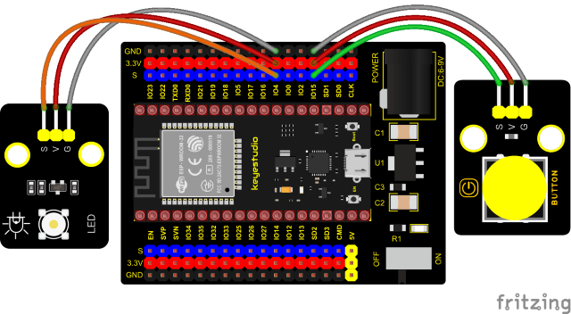
Connection Diagram
Test Code
//**********************************************************************
/*
 * Filename    : button_control_LED
 * Description : Make a table lamp.
 * Auther      : http//www.keyestudio.com
*/
#define PIN_LED    4
#define PIN_BUTTON 15
bool ledState = false;

void setup() {
  // initialize digital pin PIN_LED as an output.
  pinMode(PIN_LED, OUTPUT);
  pinMode(PIN_BUTTON, INPUT);
}

// the loop function runs over and over again forever
void loop() {
  if (digitalRead(PIN_BUTTON) == LOW) {
    delay(20);
    if (digitalRead(PIN_BUTTON) == LOW) {
      reverseGPIO(PIN_LED);
    }
    while (digitalRead(PIN_BUTTON) == LOW);
  }
}

void reverseGPIO(int pin) {
  ledState = !ledState;
  digitalWrite(pin, ledState);
}
//**********************************************************************
Test Result
Connect the wires according to the experimental wiring diagram, compile and upload the code to the ESP32. After uploading successfully,we will use a USB cable to power on. When the button is pressed, the LED will light up; when pressed again, the LED will go off.