Project 6 Principle and Application of Infrared Obstacle Detector Sensor
1.Principle
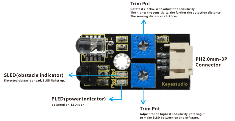
The infrared obstacle detector sensor is actually a distance-adjustable obstacle avoidance sensor designed for a wheeled robot. It has a pair of infrared transmitting and receiving tubes. The transmitter emits an infrared rays of a certain frequency. When the detection direction encounters an obstacle (reflecting surface), the infrared rays are reflected back, and receiving tube will receive it. At this time, the indicator lights up. After processed by the circuit, the signal output terminal will output Digital signal.
You can rotate the potentiometer knob on the sensor to adjust the detection distance. The effective distance is 2-40cm and the working voltage is 3.3V-5V. Due to the wide range of operating voltage, it can still work stably under the condition of relatively large fluctuating power supply voltage, suitable for use of various single-chip, Arduino controller andRaspberry Pi. Installed this sensor on the robot, make it can sense the changes in the surrounding environment. It’s really great!
2.TECH SPECS
Operating Voltage: DC 3.3-5V
Operating Current: ≥20mA
Operating Temperature: -10℃ to +50℃
Detection Distance: 2-40cm
IO Interface: 3-PIN (-/+/S/)
Output Signal: TTL level (LOW level with obstacle, HIGH level without obstacle)
Regulation Mode: multi-coil resistance regulation
Effective Angle: 35°
3.Wiring Diagram
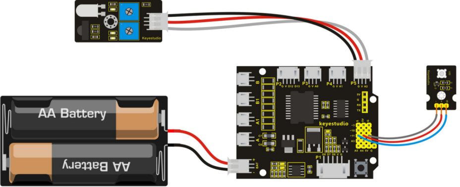
In the following, we will combine an infrared obstacle detector module and an LED module connected at pin D11 to make the application of IR obstacle avoidance. You can refer to the wiring diagram below.
4.Example Code 8 as below
Before write the code, you need to understand a common sense. On UNO board, pins D0-D13 are Digital pins, pins A0-A5 are Analog pins. Actually analog pins can also used as digital pins, like A0=14, A1=15, A2=16, A3=17, A4=18, and A5=19.
int sensorPin = 16;     // define sensor pin as A2, that is digital pin 16
int ledPin = 11;      // define LED pin as digital pin 11

void setup()
{
  pinMode(ledPin, OUTPUT); // define LED pin as OUTPUT
  pinMode(sensorPin, INPUT); // define sensor pin as INPUT
}

void loop()
{
  if (digitalRead(sensorPin)==0) // if sensor pin is read as Low level, means that obstacle is detected, to execute if function.
  {
 	digitalWrite(ledPin, HIGH); // light an LED
  }
  else
  { // or else
	digitalWrite(ledPin, LOW);  // turn off an LED
  }
}
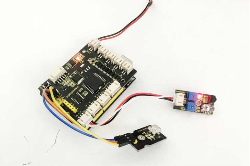
5.Example Picture
Wire it well as the above diagram, then upload the above code to the board, press down the POWER button on the shield lightly. You can also rotate the potentiometer knob on the sensor to adjust the sensitivity, just letting the right side LED on the sensor between on and off state.
Once the sensor detects an object ahead, both the right side LED on the sensor and external LED module are turned on. If no obstacle ahead, LED on the sensor and LED module are off.