Project 3: Photoresistor
(1)Description:
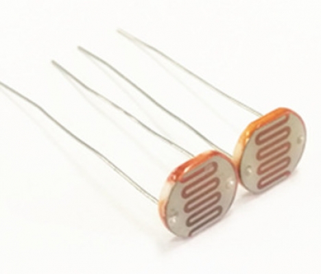
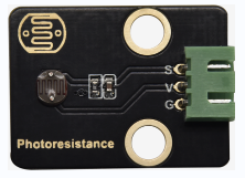
The photosensitive resistor is a special resistor made of a semiconductor material such as a sulfide or selenium, and a moisture-proof resin is also coated with a photoconductive effect. The photosensitive resistance is most sensitive to the ambient light, different illumination strength, and the resistance of the photosensitive resistance is different. We use the photosensitive resistance to design the photosensitive resistor module.
The module signal is connected to the microcontroller analog port. When the light intensity is stronger, the larger the analog port voltage, that is, the simulation value of the microcontroller is also large; in turn, when the light intensity is weaker, the smaller the analog port voltage, that is, the simulation value of the microcontroller is also small.
In this way, we can read the corresponding analog value using the photosensitive resistor module, and the intensity of the light in the inductive environment.
(2)Parameters:
Photosensitive resistance resistance value: 5K Ou-0.5m
Interface type: simulation port A0, A1
Working voltage: 3.3V-5V
Pin spacing: 2.54mm
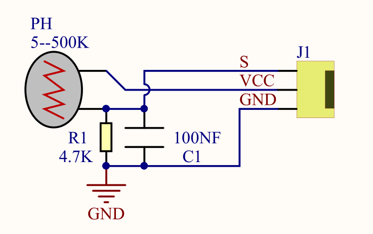
(3)Connection Diagram:
What we are going to test next isthe photoresistor module on the leftside ofthe robot
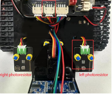
The left photoresistoris connected to A1/P3 of the motor drive shield.

(4)Test Code:
(Note: Do not connect the Bluetooth module before uploading the code, because uploading the code also uses serial communication, and there may be conflicts with the Bluetooth serial communication, which can cause the upload to fail.)
/*

Keyestudio Mini Tank Robot V3 (Popular Edition)

lesson 3.1

photocell

http://www.keyestudio.com

*/

int sensorPin = A1; // A1 is the input pin of photoresistor

int sensorValue = 0; // save the value of photoresistors

void setup()
{
	Serial.begin(9600); //Open the serial port monitor and set the baud rate to 9600
}

void loop()
{
	sensorValue = analogRead(sensorPin); //Read the analog value from the photoresistor sensor
	Serial.println(sensorValue); //The serial port prints the value of the photoresistor
	delay(500); //Delay in 500ms
}
(5)Test Results:

When covering it, the value gets smaller; if not, the value gets larger
(6)Code Explanation:
analogRead(sensorPin): read the analog value of photoresistors
Serial.begin(9600): initialize serial port and set baud rate to 9600
Serial.println: serial prints
(7)Extension Practice:
The above code just reads the value of the photoresistor. We can make the photosensitive and LED combine to change the LED.How about controlling the LED’s brightness by it?

The LED’s brightness is controlled by PWM. Therefore, we connect the LED to PMW pin(pin 9) of the shield.
Test Code
(Note: Do not connect the Bluetooth module before uploading the code, because uploading the code also uses serial communication, and there may be conflicts with the Bluetooth serial communication, which can cause the upload to fail.)
/*

Keyestudio Mini Tank Robot V3 (Popular Edition)

lesson 3.2

photocell-analog output

http://www.keyestudio.com

*/

int analogInPin = A1; // A1 is the input pin of photoresistor

int analogOutPin = 9; // Digital port 9 is the output of PMW

int sensorValue = 0; // save the variable of the resistance value of photoresistors

int outputValue = 0; // Value output to PMW

void setup()
{
	Serial.begin(9600); //Open the serial port monitor and set the baud rate to 9600
}

void loop()
{
    sensorValue = analogRead(analogInPin); //Read the analog value from thephotoresistor sensor
    // Map the analog values 0\~1023 to the PWM output values 255\~0
    outputValue = map(sensorValue, 0, 1023, 255, 0);
    // Change analog output
    analogWrite(analogOutPin, outputValue);
    Serial.println(sensorValue); //The serial port prints the value of thephotoresistor
    delay(2);
}
Upload code to the development board, then cover the photoresistor and observe the LED’s brightness.
