Project 18: BT Speed Control Robot
(1)Description:
In the previous project, we learned how to control the smart tank with Bluetooth. The PWM value of the motor we used in front of us is 200 (the speed is 200).
In this lesson, we will use Bluetooth to adjust the speed of the smart car. It is not limited to Fixed speed of 200. We define two variables to store the speed values of the left and right motors respectively. Through the previous study, we know that the range of this value can only take 0 to 255.
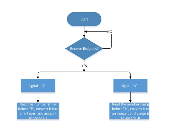
(2)Flow chart:
(3)Connection Diagram:

The GND, VCC, SDA, and SCL of the 8x16 LED dot matrix are respectively connected to-(GND), + (VCC), SDA, SCL of the expansion board;
(4)Test Code:
(Note: When uploading the code, the Bluetooth module must be unplugged, and the Bluetooth can be reconnected after the uploading process. Otherwise the code may not be burned.)
/*
  Keyestudio Mini Tank Robot V3 (Popular Edition)
  lesson 18
  bluetooth control speed tank
  http://www.keyestudio.com
*/

//Array, used to save data of images, can be calculated by yourself or gotten from modulus tool
unsigned char start01[] = {0x01, 0x02, 0x04, 0x08, 0x10, 0x20, 0x40, 0x80, 0x80, 0x40, 0x20, 0x10, 0x08, 0x04, 0x02, 0x01};
unsigned char front[] = {0x00, 0x00, 0x00, 0x00, 0x00, 0x24, 0x12, 0x09, 0x12, 0x24, 0x00, 0x00, 0x00, 0x00, 0x00, 0x00};
unsigned char back[] = {0x00, 0x00, 0x00, 0x00, 0x00, 0x24, 0x48, 0x90, 0x48, 0x24, 0x00, 0x00, 0x00, 0x00, 0x00, 0x00};
unsigned char left[] = {0x00, 0x00, 0x00, 0x00, 0x00, 0x00, 0x44, 0x28, 0x10, 0x44, 0x28, 0x10, 0x44, 0x28, 0x10, 0x00};
unsigned char right[] = {0x00, 0x10, 0x28, 0x44, 0x10, 0x28, 0x44, 0x10, 0x28, 0x44, 0x00, 0x00, 0x00, 0x00, 0x00, 0x00};
unsigned char STOP01[] = {0x2E, 0x2A, 0x3A, 0x00, 0x02, 0x3E, 0x02, 0x00, 0x3E, 0x22, 0x3E, 0x00, 0x3E, 0x0A, 0x0E, 0x00};
unsigned char clear[] = {0x00, 0x00, 0x00, 0x00, 0x00, 0x00, 0x00, 0x00, 0x00, 0x00, 0x00, 0x00, 0x00, 0x00, 0x00, 0x00};
unsigned char speed_a[] = {0x00, 0x00, 0x00, 0x20, 0x10, 0x08, 0x04, 0x02, 0xff, 0x02, 0x04, 0x08, 0x10, 0x20, 0x00, 0x00};
unsigned char speed_d[] = {0x00, 0x00, 0x00, 0x04, 0x08, 0x10, 0x20, 0x40, 0xff, 0x40, 0x20, 0x10, 0x08, 0x04, 0x00, 0x00};
#define SCL_Pin  A5  //set the pin of clock to A5
#define SDA_Pin  A4  //A4 set data pin to A4

#define ML_Ctrl 4  //define the direction control pin of the left motor
#define ML_PWM 6   //define the PWM control pins of the left motor
#define MR_Ctrl 2  //define the direction control pin of the right motor
#define MR_PWM 5   //define the PWM control pin of the right motor
char ble_val;      //define the PWM control pin of the right motor
byte speeds_L = 200; //The initial speed of the left motor is 200
byte speeds_R = 200; //The initial speed of the right motor is 200
String speeds_l, speeds_r; //Receive a string of PWM to convert to an integer PWM value

void setup()
{
  Serial.begin(9600);

  pinMode(ML_Ctrl, OUTPUT);
  pinMode(ML_PWM, OUTPUT);
  pinMode(MR_Ctrl, OUTPUT);
  pinMode(MR_PWM, OUTPUT);

  pinMode(SCL_Pin, OUTPUT);
  pinMode(SDA_Pin, OUTPUT);
  matrix_display(clear); //clear screens
  matrix_display(start01);  //show the image to start
}

void loop()
{
  if (Serial.available() > 0)
  {
    ble_val = Serial.read();
    Serial.println(ble_val);
    switch (ble_val)
    {
      case 'F':  //the command to go front
        Car_front();
        break;
      case 'B':  //the command to go back
        Car_back();
        break;
      case 'L':  //the command to turn left
        Car_left();
        break;
      case 'R':  //the command to turn right
        Car_right();
        break;
      case 'S':  //the command to stop
        Car_Stop();
        break;
      case 'u':  //Receive a string starting with u and ending with #, and convert it to an integer value
        speeds_l = Serial.readStringUntil('#');
        speeds_L = String(speeds_l).toInt();
        break;
      case 'v':  //Receive a string starting with v and ending with #, and convert it to an integer value
        speeds_r = Serial.readStringUntil('#');
        speeds_R = String(speeds_r).toInt();
        break;
    }
  }
}

/***************The function to run the motor***************/

void Car_back()
{
  digitalWrite(MR_Ctrl, LOW);
  analogWrite(MR_PWM, speeds_R);
  digitalWrite(ML_Ctrl, LOW);
  analogWrite(ML_PWM, speeds_L);
  matrix_display(back);  //Go back
}

void Car_front()
{
  digitalWrite(MR_Ctrl, HIGH);
  analogWrite(MR_PWM, 255 - speeds_R);
  digitalWrite(ML_Ctrl, HIGH);
  analogWrite(ML_PWM, 255 - speeds_L);
  matrix_display(front);  //show the image to go front
}

void Car_left()
{
  digitalWrite(MR_Ctrl, HIGH);
  analogWrite(MR_PWM, 255 - speeds_R);
  digitalWrite(ML_Ctrl, LOW);
  analogWrite(ML_PWM, speeds_L);
  matrix_display(left);  //show the image to turn left
}

void Car_right()
{
  digitalWrite(MR_Ctrl, LOW);
  analogWrite(MR_PWM, speeds_R);
  digitalWrite(ML_Ctrl, HIGH);
  analogWrite(ML_PWM, 255 - speeds_L);
  matrix_display(right);  //show the image to turn right
}

void Car_Stop()
{
  digitalWrite(MR_Ctrl, LOW);
  analogWrite(MR_PWM, 0);
  digitalWrite(ML_Ctrl, LOW);
  analogWrite(ML_PWM, 0);
  matrix_display(STOP01);  //show the image to stop
}

//This function is used for dot matrix screen display
void matrix_display(unsigned char matrix_value[])
{
  IIC_start();  //Function to call data transfer start condition
  IIC_send(0xc0);  //Choose an address
  for (int i = 0; i < 16; i++) //Pattern data has 16 bytes
  {
    IIC_send(matrix_value[i]); //transfer pattern data
  }
  IIC_end();   //End pattern data transfer
  IIC_start();
  IIC_send(0x8A);  //display control, select pulse width as 4/16
  IIC_end();
}

//Conditions for the start of data transfer
void IIC_start()
{
  digitalWrite(SDA_Pin, HIGH);
  digitalWrite(SCL_Pin, HIGH);
  delayMicroseconds(3);
  digitalWrite(SDA_Pin, LOW);
  delayMicroseconds(3);
  digitalWrite(SCL_Pin, LOW);
}

//the sign of ending data transmission
void IIC_end()
{
  digitalWrite(SCL_Pin, LOW);
  digitalWrite(SDA_Pin, LOW);
  delayMicroseconds(3);
  digitalWrite(SCL_Pin, HIGH);
  delayMicroseconds(3);
  digitalWrite(SDA_Pin, HIGH);
  delayMicroseconds(3);
}

//transfer data
void IIC_send(unsigned char send_data)
{
  for (byte mask = 0x01; mask != 0; mask <<= 1) //each character has 8 digits, which is detected one by one
  {
    if (send_data & mask)  //set high or low levels in light of each bit(0 or 1)
    {
      digitalWrite(SDA_Pin, HIGH);
    }
    else
    {
      digitalWrite(SDA_Pin, LOW);
    }
    delayMicroseconds(3);
    digitalWrite(SCL_Pin, HIGH); //Pull the clock pin SCL_Pin high to stop data transmission
    delayMicroseconds(3);
    digitalWrite(SCL_Pin, LOW); //pull down the clock pin SCL_Pin to change signals of SDA
  }
}
(5)Test Results:
After uploading the test code successfully, dialing the DIP switch to the right end, powering it on, and pairing the APP with Bluetooth, the smart car can be controlled to move by the APP. And the speed of the car can be regulated by pulling the speed dials of the left and right motors.
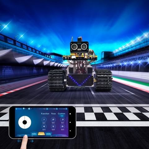
(You can refer to function table in project 17 )