Project 17: Bluetooth Control Tank
(1)Description:
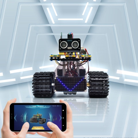
We have learned the basic knowledge of Bluetooth in the previous project . In this lesson, we will use Bluetooth to control the smart car. Since it involves Bluetooth, a sending end and a receiving end are needed. In the project, we use the mobile phone as the sender (master), and the smart car connected with the HM-10 Bluetooth module (slave) as the receiver.
We have learned earlier that sending a bit can control LEDs. And the principle of controlling this robot car is the same.
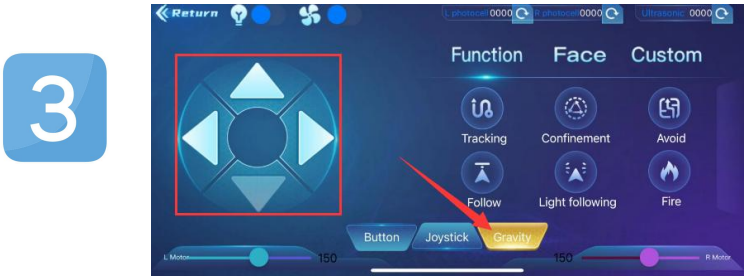
We first understand the function of each button on the APP, and then use the button on the APP to control the tank.
(2)Key Function on the APP
The following table illustrates the functions of corresponding keys:
KEYS |
FUNCTIONS |
|---|---|
|
Pair and connect HM-10 Bluetooth module; click again to disconnect |
|
select the robot to operate |
|
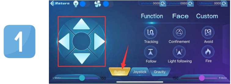
to control the movements of the robot by buttons |
|
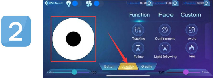
To control the movements of the robot by joystick |
|
To control the movements of the robot by gravity |
|
Send “F”when pressed and “S”when released |
|
Send “L”when pressed and “S”when released |
|
Send “R”when pressed and “S”when released |
|
Send “B”when pressed and “S”when released |
|
Send “u”+digit+“#”when dragged |
|
Send “v”+digit+“#”when dragged |
|
Select to enter Function page |
|
Send “G”when pressed and “S”when pressed again |
|
Send “h”when pressed and “S”when pressed again |
|
Send “e”when pressed and “S”when pressed again |
|
Send “f”when pressed and “S”when pressed again |
|
Send “i”when pressed and “S”when pressed again |
|
Send “j”when pressed and “S”when pressed again |
|
Select to enter facial expression display mode |
|
Send “k”when pressed and “z”when pressed again |
|
Send “l”when pressed and “z”when pressed again |
|
Send “m”when pressed and “z”when pressed again |
|
Send “n”when pressed and “z”when pressed again |
|
Send “o”when pressed and “z”when pressed again |
|
Send “p”when pressed and “z”when pressed again |
|
Choose to enter the custom function interface; there are six keys 1,2,3,4,5,6; with these keys, you can expand some functions by yourself |
|
Click to send “w” |
|
Click to send“y” |
|
Click to send“x” |
|
Click to send“c” Click again to send“d” |


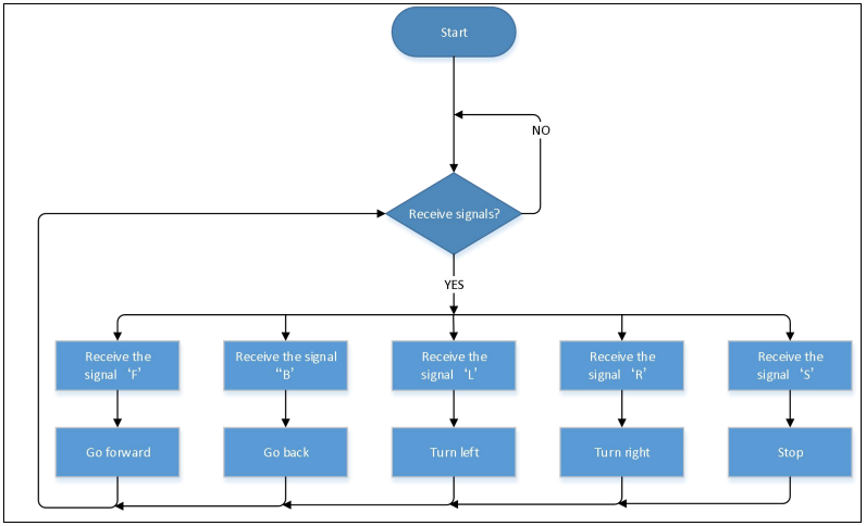
(3)Flow Chart:
(4)Wiring Diagram:

The GND, VCC, SDA, and SCL of the 8x16 LED dot matrix are respectively connected to-(GND), + (VCC), SDA, SCL of the expansion board;
The STATE and BRK pins of the Bluetooth module do not need to be connected.
(5)Test Code:
(Note: When uploading the code, the Bluetooth module must be unplugged, and the Bluetooth can be reconnected after the uploading process. Otherwise, the code may not be uploaded successfully.)
/*
  Keyestudio Mini Tank Robot V3 (Popular Edition)
  lesson 17.
  bluetooth Control tank
  http://www.keyestudio.com
*/

//Array, used to save data of images, can be calculated by yourself or gotten from modulus tool
unsigned char start01[] = {0x01, 0x02, 0x04, 0x08, 0x10, 0x20, 0x40, 0x80, 0x80, 0x40, 0x20, 0x10, 0x08, 0x04, 0x02, 0x01};
unsigned char front[] = {0x00, 0x00, 0x00, 0x00, 0x00, 0x24, 0x12, 0x09, 0x12, 0x24, 0x00, 0x00, 0x00, 0x00, 0x00, 0x00};
unsigned char back[] = {0x00, 0x00, 0x00, 0x00, 0x00, 0x24, 0x48, 0x90, 0x48, 0x24, 0x00, 0x00, 0x00, 0x00, 0x00, 0x00};
unsigned char left[] = {0x00, 0x00, 0x00, 0x00, 0x00, 0x00, 0x44, 0x28, 0x10, 0x44, 0x28, 0x10, 0x44, 0x28, 0x10, 0x00};
unsigned char right[] = {0x00, 0x10, 0x28, 0x44, 0x10, 0x28, 0x44, 0x10, 0x28, 0x44, 0x00, 0x00, 0x00, 0x00, 0x00, 0x00};
unsigned char STOP01[] = {0x2E, 0x2A, 0x3A, 0x00, 0x02, 0x3E, 0x02, 0x00, 0x3E, 0x22, 0x3E, 0x00, 0x3E, 0x0A, 0x0E, 0x00};
unsigned char clear[] = {0x00, 0x00, 0x00, 0x00, 0x00, 0x00, 0x00, 0x00, 0x00, 0x00, 0x00, 0x00, 0x00, 0x00, 0x00, 0x00};
#define SCL_Pin  A5  //设Set the clock pin as A5
#define SDA_Pin  A4  //Set the data pin as A4

#define ML_Ctrl 4  //Define the direction control pin of the left motor
#define ML_PWM 6   //Define the PWM control pin of the left motor
#define MR_Ctrl 2  //Define the direction control pin of the right motor
#define MR_PWM 5   //Define the PWM control pin of the right motor
char ble_val;      //Used to store the value obtained by Bluetooth

void setup()
{
  Serial.begin(9600);

  pinMode(ML_Ctrl, OUTPUT);
  pinMode(ML_PWM, OUTPUT);
  pinMode(MR_Ctrl, OUTPUT);
  pinMode(MR_PWM, OUTPUT);

  pinMode(SCL_Pin, OUTPUT);
  pinMode(SDA_Pin, OUTPUT);
  matrix_display(clear); //clear screens
  matrix_display(start01);  //show the image to start
}

void loop()
{
  if (Serial.available())
  {
    ble_val = Serial.read();
    Serial.println(ble_val);
  }
  switch (ble_val)
  {
    case 'F':  //the command to go front
      Car_front();
      break;
    case 'B':  //the command to go back
      Car_back();
      break;
    case 'L':  //the command to turn left
      Car_left();
      break;
    case 'R':  //the command to turn right
      Car_right();
      break;
    case 'S':  //the command to stop
      Car_Stop();
      break;
  }
}

/***************The function to run the motor***************/
void Car_back()
{
  digitalWrite(MR_Ctrl, LOW);
  analogWrite(MR_PWM, 200);
  digitalWrite(ML_Ctrl, LOW);
  analogWrite(ML_PWM, 200);
  matrix_display(back);  //Go back
}

void Car_front()
{
  digitalWrite(MR_Ctrl, HIGH);
  analogWrite(MR_PWM, 55);
  digitalWrite(ML_Ctrl, HIGH);
  analogWrite(ML_PWM, 55);
  matrix_display(front);  //show the image to go front
}

void Car_left()
{
  digitalWrite(MR_Ctrl, HIGH);
  analogWrite(MR_PWM, 55);
  digitalWrite(ML_Ctrl, LOW);
  analogWrite(ML_PWM, 200);
  matrix_display(left);  //show the image to turn lefr
}

void Car_right()
{
  digitalWrite(MR_Ctrl, LOW);
  analogWrite(MR_PWM, 200);
  digitalWrite(ML_Ctrl, HIGH);
  analogWrite(ML_PWM, 55);
  matrix_display(right);  //show the image to turn right
}

void Car_Stop()
{
  digitalWrite(MR_Ctrl, LOW);
  analogWrite(MR_PWM, 0);
  digitalWrite(ML_Ctrl, LOW);
  analogWrite(ML_PWM, 0);
  matrix_display(STOP01);  //show the image to stop
}

//This function is used for dot matrix screen display
void matrix_display(unsigned char matrix_value[])
{
  IIC_start();  //Function to call data transfer start condition
  IIC_send(0xc0);  //Choose an address
  for (int i = 0; i < 16; i++) //Pattern data has 16 bytes
  {
    IIC_send(matrix_value[i]); //transfer pattern data
  }
  IIC_end();   //End pattern data transfer
  IIC_start();
  IIC_send(0x8A);  //display control, select pulse width as 4/16
  IIC_end();
}

//Conditions for the start of data transfer
void IIC_start()
{
  digitalWrite(SDA_Pin, HIGH);
  digitalWrite(SCL_Pin, HIGH);
  delayMicroseconds(3);
  digitalWrite(SDA_Pin, LOW);
  delayMicroseconds(3);
  digitalWrite(SCL_Pin, LOW);
}

//the sign of ending data transmission
void IIC_end()
{
  digitalWrite(SCL_Pin, LOW);
  digitalWrite(SDA_Pin, LOW);
  delayMicroseconds(3);
  digitalWrite(SCL_Pin, HIGH);
  delayMicroseconds(3);
  digitalWrite(SDA_Pin, HIGH);
  delayMicroseconds(3);
}

//transfer data
void IIC_send(unsigned char send_data)
{
  for (byte mask = 0x01; mask != 0; mask <<= 1) //each character has 8 digits, which is detected one by one
  {
    if (send_data & mask)  //set high or low levels in light of each bit(0 or 1)
    {
      digitalWrite(SDA_Pin, HIGH);
    }
    else
    {
      digitalWrite(SDA_Pin, LOW);
    }
    delayMicroseconds(3);
    digitalWrite(SCL_Pin, HIGH); //Pull the clock pin SCL_Pin high to stop data transmission
    delayMicroseconds(3);
    digitalWrite(SCL_Pin, LOW); //pull down the clock pin SCL_Pin to change signals of SDA
  }
}
(6)Test Result:
After uploading the code, connect the robot to the Bluetooth module and pair the Bluetooth APP. Turn on the powerswitch of the motor drive shield. Place the robot on the floor, you can use these buttons of the Bluetooth app to control the robot.
The up, down, left and right arrows control the robot to move forward, backward, left and right respectively.
Click the joystick button and pull the direction of the black point in the white circle to control the movement direction of the robot.
3.Click the Gravity button and tilt the phone in the forward, backward, left, and right directions, and the robot will move in the direction in which the phone istilted.