Project 8: Motor Driving and Speed Control
(1)Description:
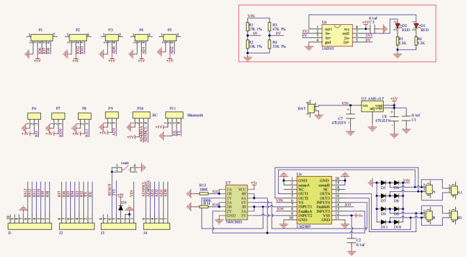
There are many ways to drive motors. Our smart car uses the most common solution called L298P. L298P, produced by STMicroelectronics, is an excellent driving chip specially designed for driving high-power motors .
It can directly drive DC motors, two-phase and four-phase motors with the driving current reaching 2A. And the motor’s output terminal adopts 8 high-speed Schottky diodes as protection.
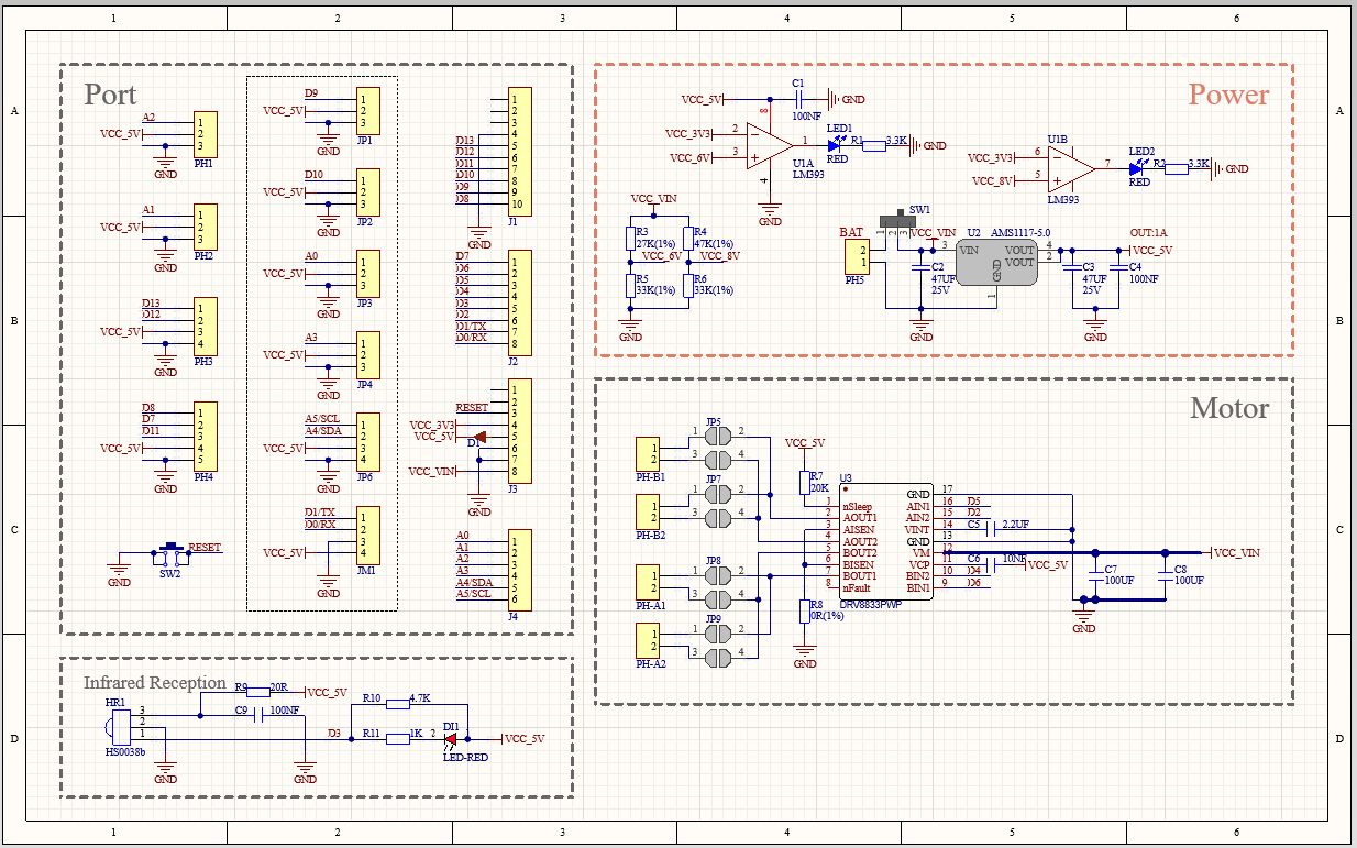
We have designed an expansion board based on the L298P circuit of which the laminated design can be directly plugged into the UNO R3 board for use reducing the technical difficulties for users in using and driving the motor.
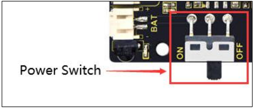
Stack the expansion board on the board, power the BAT , turn the DIP switch to the ON end, and power the expansion board and the UNO R3 board at the same time via external power supply.
In order to facilitate wiring, the expansion board is equipped with anti-reverse interface (PH2.0 -2P -3P -4P -5P) and thus it can be directly plug with motors, power supply, and sensors /modules.
The Bluetooth interface of the drive expansion board is fully compatible with the Keyestudio HM-10 Bluetooth module. Therefore, we only need to insert the HM-10 Bluetooth module into the corresponding interface when connecting.
At the same time, the drive extension board also uses 2.54 pin headers to extend out some available digital ports and analog ports, so that you can continue to add other sensors and carry out expansion experiments.
The expansion board can be connected to 4 DC motors. In the default jumper cap connection mode, the A and A1, B and B1 interface motors are connected in parallel, and their motion pattern is the same. 8 jumper caps can be used to control the rotation direction of the 4 motor interfaces.
For example, when the two jumper caps in front of the motor A interface are changed from a horizontal connection to a vertical connection, the rotation direction of the motor A now is opposite to the original rotation direction.
(2)Parameters:
Logic part input voltage: DC 5V
Driving part input voltage: DC 7-12V
Logic part working current: ≤36mA
Driving part working current: ≤ 2A
Maximum dissipation power: 25W (T=75℃)
Control signal input level:
High level: 2.3V ≤ Vin ≤ 5V
Low level: 0V ≤ Vin ≤ 1.5V
Working temperature: -25℃~+130℃
(3)Drive the robot to move
The direction pin of A motor is D2, the speed control pin is D5; the direction pin of B motor is in D4 and the speed control pin is D6,
According to the table below, we can know how to control the movement of the robot by controlling the rotation of two motors through the digital ports and PWM ports . Among them, the range of PWM value is 0-255. The larger the value is, the faster the motor rotates.
Function |
D4 |
D6(PWM) |
Motor (left)B |
D2 |
D5(PWM) |
Motor(Right)A |
|---|---|---|---|---|---|---|
Move Forward |
HIGH |
255-200 |
Rotate Left |
HIGH |
255-200 |
Rotate Left |
Go Back |
LOW |
200 |
Rotate Right |
LOW |
200 |
Rotate Right |
Rotate Left |
LOW |
200 |
Rotate Right |
HIGH |
255-200 |
Rotate Left |
Rotate Right |
HIGH |
255-200 |
Rotate Left |
LOW |
200 |
Rotate Right |
Stop |
LOW |
0 |
Stop |
LOW |
0 |
Stop |
(4)Connection Diagram:
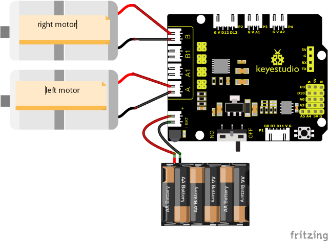
Note:
The 4-pin connector is marked with A, A1, B1 and B. The right rear motor is connected to B of the 8833 board and left front one is connected to A port.
(5)Test Code:
(Note: Do not connect the Bluetooth module before uploading the code, because uploading the code also uses serial communication, and there may be conflicts with the Bluetooth serial communication, which can cause the upload to fail.)
/*
Keyestudio Mini Tank Robot V3 (Popular Edition)
lesson 8.1
motor driver
http://www.keyestudio.com
*/

#define ML_Ctrl 4 //Define the direction control pin of the left motor
#define ML_PWM 6 //Define the PWM control pin of the left motor
#define MR_Ctrl 2 //Define the direction control pin of the right motor
#define MR_PWM 5 //Define the PWM control pin of the right motor

void setup()
{
    pinMode(ML_Ctrl, OUTPUT);//Define the direction control pin of the left motor as OUTPUT
    pinMode(ML_PWM, OUTPUT);//Define the PWM control pin of the left motor as OUTPUT
    pinMode(MR_Ctrl, OUTPUT);//Define the direction control pin of the right motor as OUTPUT
    pinMode(MR_PWM, OUTPUT);//Define the PWM control pin of the right motor as OUTPUT
}

void loop()
{
    //front
    digitalWrite(ML_Ctrl, HIGH); //Set direction control speed of the left motor to HIGH
    analogWrite(ML_PWM, 55); //PWM control speed of the left motor is 55
    digitalWrite(MR_Ctrl, HIGH); //Set direction control speed of the right motor to HIGH
    analogWrite(MR_PWM, 55); //PWM control speed of the right motor is 55
    delay(2000);//delay in 2s

    //back
    digitalWrite(ML_Ctrl, LOW); //Set direction control speed of the left motor to LOW
    analogWrite(ML_PWM, 200); //PWM control speed of the left motor is 200
    digitalWrite(MR_Ctrl, LOW); //Set direction control speed of the right motor to LOW
    analogWrite(MR_PWM, 200); //PWM control speed of the right motor is 200
    delay(2000);//delay in 2s

    //turn left
    digitalWrite(ML_Ctrl, LOW); //Set direction control speed of the left motor to LOW
    analogWrite(ML_PWM, 200); //PWM control speed of the left motor is 200
    digitalWrite(MR_Ctrl, HIGH); //Set direction control speed of the right motor to HIGH
    analogWrite(MR_PWM, 55); //PWM control speed of the right motor is 55
    delay(2000);//delay in 2s

    //turn right
    digitalWrite(ML_Ctrl, HIGH); //Set direction control speed of the left motor to HIGH
    analogWrite(ML_PWM, 55); //PWM control speed of the left motor is 55
    digitalWrite(MR_Ctrl, LOW); //Set direction control speed of the right motor to LOW
    analogWrite(MR_PWM, 200); //PWM control speed of the right motor is 200
    delay(2000);//delay in 2s

    //stop
    digitalWrite(ML_Ctrl, LOW);
    analogWrite(ML_PWM, 0); //PWM control speed of the left motor is 0
    digitalWrite(MR_Ctrl, LOW);
    analogWrite(MR_PWM, 0); //PWM control speed of the right motor is 0
    delay(2000);//delay in 2s
}
(6)Test Results:
After wiring according to the diagram, uploading the test code and powering it up.
the smart car moves forward for 2s, steps back for 2s, turns left for 2s, turns right for 2s and stops for 2s and repeats this sequence.
(7)Code Explanation:
digitalWrite(ML_Ctrl,LOW);
The change between high and low levels can makes motors to rotate clockwise or anticlockwise. General digital pins can be used to control these movements.
analogWrite(ML_PWM,200);
The speed adjustment of the motor is realized by PWM, and the pin that controls the speed of the motor must be the PWM pin of Arduino.
(8)Expansion Project:
We adjust the speed of motors by controlling PWM and the wiring remains the same.
Test Code
(Note: Do not connect the Bluetooth module before uploading the code, because uploading the code also uses serial communication, and there may be conflicts with the Bluetooth serial communication, which can cause the upload to fail.)
/*
Keyestudio Mini Tank Robot V3 (Popular Edition)
lesson 8.2
motor driver pwm
http://www.keyestudio.com
*/

#define ML_Ctrl 4 //Define the direction control pin of the left motor
#define ML_PWM 6 //Define the PWM control pin of the left motor
#define MR_Ctrl 2 //Define the direction control pin of the right motor
#define MR_PWM 5 //Define the PWM control pin of the right motor

void setup()
{
    pinMode(ML_Ctrl, OUTPUT);//Define the direction control pin of the left motor as OUTPUT
    pinMode(ML_PWM, OUTPUT);//Define the PWM control pin of the left motor as OUTPUT
    pinMode(MR_Ctrl, OUTPUT);//Define the direction control pin of the right motor as OUTPUT
    pinMode(MR_PWM, OUTPUT);//Define the PWM control pin of the right motor as OUTPUT
}

void loop()
{
    //front
    digitalWrite(ML_Ctrl, HIGH); //Set direction control speed of the left motor to HIGH
    analogWrite(ML_PWM, 155); //PWM control speed of the left motor is 155
    digitalWrite(MR_Ctrl, HIGH); //Set direction control speed of the right motor to HIGH
    analogWrite(MR_PWM, 155); //PWM control speed of the right motor is 155
    delay(2000);//delay in 2s

    //back
    digitalWrite(ML_Ctrl, LOW); //Set direction control speed of the left motor to LOW
    analogWrite(ML_PWM, 100); //PWM control speed of the left motor is 100
    digitalWrite(MR_Ctrl, LOW); //Set direction control speed of the right motor to LOW
    analogWrite(MR_PWM, 100); //PWM control speed of the right motor is 100
    delay(2000);//delay in 2s

    //left
    digitalWrite(ML_Ctrl, LOW); //Set direction control speed of the left motor to LOW
    analogWrite(ML_PWM, 100); //PWM control speed of the left motor is 100
    digitalWrite(MR_Ctrl, HIGH); //Set direction control speed of the right motor to HIGH
    analogWrite(MR_PWM, 155); //PWM control speed of the right motor is 155
    delay(2000);//delay in 2s

    //right
    digitalWrite(ML_Ctrl, HIGH); //Set direction control speed of the left motor to HIGH
    analogWrite(ML_PWM, 155); //PWM control speed of the left motor is 155
    digitalWrite(MR_Ctrl, LOW); //Set direction control speed of the right motor to LOW
    analogWrite(MR_PWM, 100); //PWM control speed of the right motor is 100
    delay(2000);//delay in 2s

    //stop
    digitalWrite(ML_Ctrl, LOW); //Set direction control speed of the left motor to LOW
    analogWrite(ML_PWM, 0); //PWM control speed of the left motor is 0
    digitalWrite(MR_Ctrl, LOW); //Set direction control speed of the right motor to LOW
    analogWrite(MR_PWM, 0); //PWM control speed of the right motor is 0
    delay(2000);//delay in 2s
}
Upload the code, the speed of the motor is slower.
Low current will cause the motor to rotate slowly.