Project 10 Photo Resistor
1. Introduction After completing all the previous experiments, you may acquire some basic understanding and knowledge about Arduino application. We have introduced digital input and output, analog input and PWM. Now, let’s begin the learning of sensors applications.
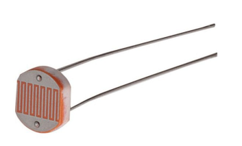
Photo resistor (Photovaristor) is a resistor whose resistance varies from the different incident light strength. It’s made based on the photoelectric effect of semiconductor. If the incident light is intense, its resistance reduces; if the incident light is weak, the resistance increases.
Photovaristor is commonly applied in the measurement of light, light control and photovoltaic conversion (convert the change of light into the change of electricity).
Photo resistor is also widely applied to various light control circuit, such as light control and adjustment, optical switches, etc.
We will start with a relatively simple experiment regarding to photovaristor application. Photovaristor is an element that will change its resistance as light strength changes. So need to read the analog values.
You can refer to the PWM experiment, replacing the potentiometer with photovaristor. When there is change in light strength, it will cause corresponding change on the LED.
2. Hardware Required:
Photo resistor*1
Red M5 LED*1
10KΩresistor*1
220Ωresistor*1
Breadboard*1
Breadboard jumper wires*several
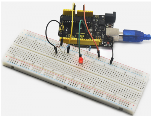
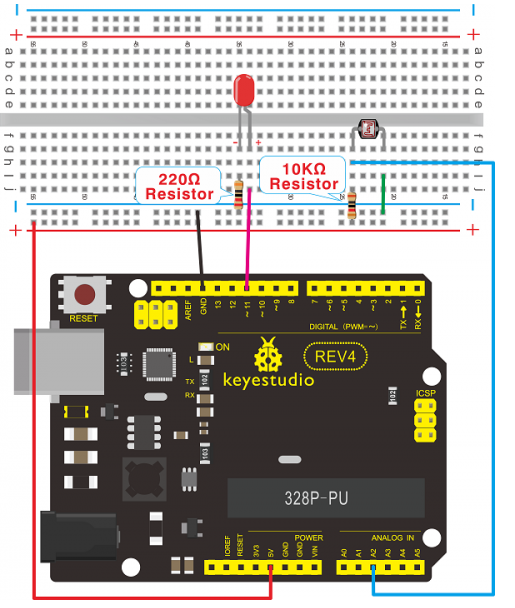
3. Connection for REV4
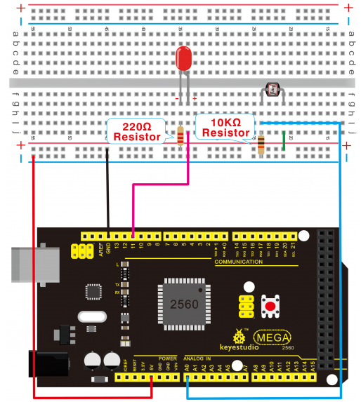
4. Connection for 2560 R3
5. Sample Code After the connection, let’s begin the program compiling. The program is similar to the one of PWM. For change detail, please refer to the sample program below.
int potpin=0;// initialize analog pin 0, connected with photovaristor
int ledpin=11;// initialize digital pin 11, output regulating the brightness of LED
int val=0;// initialize variable va

void setup()
{
    pinMode(ledpin,OUTPUT);// set digital pin 11 as “output”
    Serial.begin(9600);// set baud rate at “9600”
}

void loop()
{
    val=analogRead(potpin);// read the analog value of the sensor and assign it to val
    Serial.println(val);// display the value of val
    analogWrite(ledpin,val/4);// turn on the LED and set up brightness(maximum output value 255)
    delay(10);// wait for 0.01
}
6. Result After downloading the program, you can change the light strength around the photovaristor and see corresponding brightness change of the LED.
Photovaristors has various applications in our everyday life. You can make other interesting interactive projects based on this one.