Project 20 1602 LCD
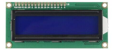
1. Introduction In this experiment, we use an Arduino to drive the 1602 LCD.1602 LCD has wide applications. In the beginning,1602 LCD uses a HD44780 controller. Now, almost all 1602 LCD module uses a compatible IC, but their features are basically the same.
2. 1602LCD Parameters
Display Capacity: 16 × 2 characters
Chip Operating Voltage: 4.5 ~ 5.5V
Working Current: 2.0mA (5.0V)
Optimum working voltage of the module is 5.0V
Character Size: 2.95 * 4.35 (W * H) mm
3. Pin Description of 1602 LCD
No. |
Mark |
Pin Description |
No. |
Mark |
Pin Description |
|---|---|---|---|---|---|
1 |
VSS |
Power GND |
9 |
D2 |
Date I/O |
2 |
VDD |
Power Positive |
10 |
D3 |
Date I/O |
3 |
VL |
LCD Voltage Bias Signal |
11 |
D4 |
Date I/O |
4 |
RS |
Select data/command(V/L) |
12 |
D5 |
Date I/O |
5 |
R/W |
Select read/write(H/L) |
13 |
D6 |
Date I/O |
6 |
E |
Enable Signal |
14 |
D7 |
Date I/O |
7 |
D0 |
Date I/O |
15 |
BLA |
Back Light Power Positive |
8 |
D1 |
Date I/O |
16 |
BLK |
Back Light Power Negative |
4. Interface Description
two power sources, one for module power, another one for backlight, generally use 5V. In this project, we use 3.3V for backlight.
VL is the pin for adjusting contrast ratio; it usually connects a potentiometer(no more than 5KΩ) in series for its adjustment.
In this experiment, we use a 1KΩ resistor. For the connection, it has 2 methods, namely high potential and low potential. Here, we use low potential method; connect the resistor and then the GND.
RS is a very common pin in LCD. It’s a selecting pin for command/data. When the pin is in high level, it’s in data mode; when it’s in low level, it’s in command mode.
RW pin is also very common in LCD. It’s a selecting pin for read/write. When the pin is in high level, it’s in read operation; when it’s in low level, it’s in write operation.
E pin is also very common in LCD. Usually, when the signal in the bus is stabilized, it sends out a positive pulse requiring read operation. When this pin is in high level, the bus is not allowed to have any change.
D0-D7 is 8-bit bidirectional parallel bus, used for command and data transmission.
BLA is anode for back light; BLK, cathode for back light.
5. Basic Operations of 1602LCD
Read status |
input |
RS=L, R/W=H, E=H |
output |
D0-D7=status word |
|---|---|---|---|---|
Write command |
input |
RS=L, R/W=H, D0-D7=command code, E=high pulse |
output |
none |
Read data |
input |
RS=H, R/W=H, E=H |
output |
D0-D7=data |
Write data |
input |
RS=H, R/W=L, D0-D7=data, E=high pulse |
output |
none |
6. Hardware Required
1 * Controller board
1 * 1602 LCD
1 * Breadboard
1 * potentiometer
1 * USB cable
16 *Jumper wires
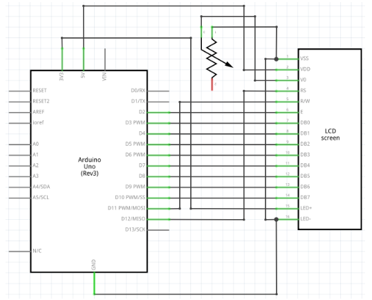
7. Connection & Sample Program
1602 can directly communicate with Arduino. According to the product manual, it has two connection methods, namely 8-bit connection and 4-bit connection.
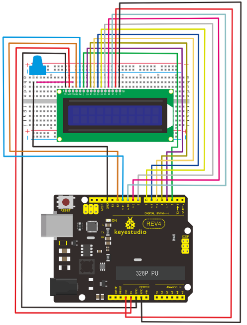
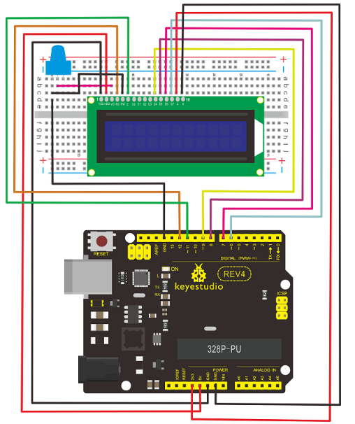
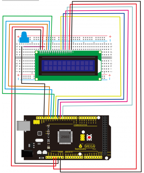
8-bit connection method
Connection for REV4
Connection for 2560 R3

8. Sample Code A
int DI = 12;
int RW = 11;
int DB[] = {3, 4, 5, 6, 7, 8, 9, 10};// use array to select pin for bus
int Enable = 2;
void LcdCommandWrite(int value)
{
// define all pins
int i = 0;
for (i=DB[0]; i <= DI; i++) // assign value for bus
{
digitalWrite(i,value & 01);// for 1602 LCD, it uses D7-D0( not D0-D7) for signal identification; here, it’s used for signal inversion.
value >>= 1;
}
digitalWrite(Enable,LOW);
delayMicroseconds(1);
digitalWrite(Enable,HIGH);
delayMicroseconds(1); // wait for 1ms
digitalWrite(Enable,LOW);
delayMicroseconds(1); // wait for 1ms
}
void LcdDataWrite(int value)
{
// initialize all pins
int i = 0;
digitalWrite(DI, HIGH);
digitalWrite(RW, LOW);
for (i=DB[0]; i <= DB[7]; i++)
{
digitalWrite(i,value & 01);
value >>= 1;
}
digitalWrite(Enable,LOW);
delayMicroseconds(1);
digitalWrite(Enable,HIGH);
delayMicroseconds(1);
digitalWrite(Enable,LOW);
delayMicroseconds(1); // wait for 1ms
}
void setup (void)
{
int i = 0;
for (i=Enable; i <= DI; i++)
{
pinMode(i,OUTPUT);
}
delay(100);
// initialize LCD after a brief pause
// for LCD control
LcdCommandWrite(0x38); // select as 8-bit interface, 2-line display, 5x7 character size
delay(64);
LcdCommandWrite(0x38); // select as 8-bit interface, 2-line display, 5x7 character size
delay(50);
LcdCommandWrite(0x38); // select as 8-bit interface, 2-line display, 5x7 character size
delay(20);
LcdCommandWrite(0x06); // set input mode
// auto-increment, no display of shifting
delay(20);
LcdCommandWrite(0x0E); // display setup
// turn on the monitor, cursor on, no flickering
delay(20);
LcdCommandWrite(0x01); // clear the screen, cursor position returns to 0
delay(100);
LcdCommandWrite(0x80); // display setup
// turn on the monitor, cursor on, no flickering
delay(20);
}
void loop (void)
{
LcdCommandWrite(0x01); // clear the screen, cursor position returns to 0
delay(10);
LcdCommandWrite(0x80+3);
delay(10);
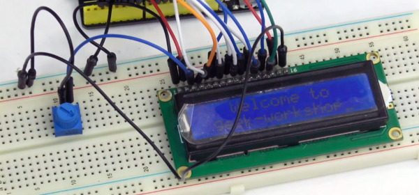
// write in welcome message
LcdDataWrite('W');
LcdDataWrite('e');
LcdDataWrite('l');
LcdDataWrite('c');
LcdDataWrite('o');
LcdDataWrite('m');
LcdDataWrite('e');
LcdDataWrite(' ');
LcdDataWrite('t');
LcdDataWrite('o');
delay(10);
LcdCommandWrite(0xc0+1); // set cursor position at second line, second position
delay(10);
LcdDataWrite('g');
LcdDataWrite('e');
LcdDataWrite('e');
LcdDataWrite('k');
LcdDataWrite('-');
LcdDataWrite('w');
LcdDataWrite('o');
LcdDataWrite('r');
LcdDataWrite('k');
LcdDataWrite('s');
LcdDataWrite('h');
LcdDataWrite('o');
LcdDataWrite('p');
delay(5000);
LcdCommandWrite(0x01); // clear the screen, cursor returns to 0
delay(10);
LcdDataWrite('I');
LcdDataWrite(' ');
LcdDataWrite('a');
LcdDataWrite('m');
LcdDataWrite(' ');
LcdDataWrite('h');
LcdDataWrite('o');
LcdDataWrite('n');
LcdDataWrite('g');
LcdDataWrite('y');
LcdDataWrite('i');
delay(3000);
LcdCommandWrite(0x02); // set mode as new characters replay old ones, where there is no new ones remain the same.
delay(10);
LcdCommandWrite(0x80+5); // set cursor position at first line, sixth position
delay(10);
LcdDataWrite('t');
LcdDataWrite('h');
LcdDataWrite('e');
LcdDataWrite(' ');
LcdDataWrite('a');
LcdDataWrite('d');
LcdDataWrite('m');
LcdDataWrite('i');
LcdDataWrite('n');
delay(5000);
}
9. 4-bit connection method: When using this module, 8-bit connection uses all the digital pins of the Arduino, leaving no pin for sensors. What then? you can use 4-bit connection.
Connection for REV4:
Connection for 2560 R3
After the connection, upload below code to the controller board and see how it goes.
10. Sample Code B
int LCD1602_RS=12;
int LCD1602_RW=11;
int LCD1602_EN=10;
int DB[] = { 6, 7, 8, 9};
char str1[]="Welcome to";
char str2[]="geek-workshop";
char str3[]="this is the";
char str4[]="4-bit interface";

void LCD_Command_Write(int command)
{
    int i,temp;
    digitalWrite( LCD1602_RS,LOW);
    digitalWrite( LCD1602_RW,LOW);
    digitalWrite( LCD1602_EN,LOW);
    temp=command & 0xf0;
    for (i=DB[0]; i <= 9; i++)
    {
       digitalWrite(i,temp & 0x80);
       temp <<= 1;
    }
    digitalWrite( LCD1602_EN,HIGH);
    delayMicroseconds(1);
    digitalWrite( LCD1602_EN,LOW);
    temp=(command & 0x0f)<<4;
    for (i=DB[0]; i <= 10; i++)
    {
       digitalWrite(i,temp & 0x80);
       temp <<= 1;
    }
    digitalWrite( LCD1602_EN,HIGH);
    delayMicroseconds(1);
    digitalWrite( LCD1602_EN,LOW);
}

void LCD_Data_Write(int dat)
{
    int i=0,temp;
    digitalWrite( LCD1602_RS,HIGH);
    digitalWrite( LCD1602_RW,LOW);
    digitalWrite( LCD1602_EN,LOW);
    temp=dat & 0xf0;
    for (i=DB[0]; i <= 9; i++)
    {
       digitalWrite(i,temp & 0x80);
       temp <<= 1;
    }
    digitalWrite( LCD1602_EN,HIGH);
    delayMicroseconds(1);
    digitalWrite( LCD1602_EN,LOW);
    temp=(dat & 0x0f)<<4;
    for (i=DB[0]; i <= 10; i++)
    {
       digitalWrite(i,temp & 0x80);
       temp <<= 1;
    }
    digitalWrite( LCD1602_EN,HIGH);
    delayMicroseconds(1);
    digitalWrite( LCD1602_EN,LOW);
}

void LCD_SET_XY( int x, int y )
{
  int address;
  if (y ==0)    address = 0x80 + x;
  else          address = 0xC0 + x;
  LCD_Command_Write(address);
}

void LCD_Write_Char( int x,int y,int dat)
{
  LCD_SET_XY( x, y );
  LCD_Data_Write(dat);
}

void LCD_Write_String(int X,int Y,char *s)
{
    LCD_SET_XY( X, Y );    // address setup
    while (*s)             // write character string
    {
      LCD_Data_Write(*s);
      s ++;
    }
}

void setup (void)
{
  int i = 0;
  for (i=6; i <= 12; i++)
   {
     pinMode(i,OUTPUT);
   }
  delay(100);
  LCD_Command_Write(0x28);// 4 wires, 2 lines 5x7
  delay(50);
  LCD_Command_Write(0x06);

 delay(50);
  LCD_Command_Write(0x0c);
  delay(50);
  LCD_Command_Write(0x80);
  delay(50);
  LCD_Command_Write(0x01);
  delay(50);

}

void loop (void)
{
   LCD_Command_Write(0x01);
   delay(50);
   LCD_Write_String(3,0,str1);// line 1, start at the fourth address
   delay(50);
   LCD_Write_String(1,1,str2);// line 2, start at the second address
   delay(5000);
   LCD_Command_Write(0x01);
   delay(50);
   LCD_Write_String(0,0,str3);
   delay(50);
   LCD_Write_String(0,1,str4);
   delay(5000);
}