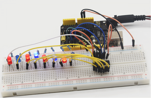
Project 16 74HC595
1. Introduction To put it simply, 74HC595 is a combination of 8-digit shifting register, memorizer and equipped with tri-state output. Here, we use it to control 8 LEDs.
You may wonder why use a 74HC595 to control LED? Well, think about how many I/O it takes for an Arduino to control 8 LEDs? Yes, 8.
For an Arduino, it has only 20 I/O including analog ports. So, to save port resources, we use 74HC595 to reduce the number of ports it needs. Using 74HC595 enables us to use 3 digital I/O port to control 8 LEDs!
The 74HC595 devices contain an 8-bit serial-in, parallel-out shift register that feeds an 8-bit D-type storage register. The storage register has parallel 3-state outputs. Separate clocks are provided for both the shift and storage register.
The shift register has a direct overriding clear (SRCLR) input, serial (SER) input, and serial outputs for cascading. When the output-enable (OE) input is high, the outputs are in the high-impedance state. Both the shift register clock (SRCLK) and storage register clock (RCLK) are positive-edge triggered. If both clocks are connected together, the shift register always is one clock pulse ahead of the storage register.
2. Hardware Required
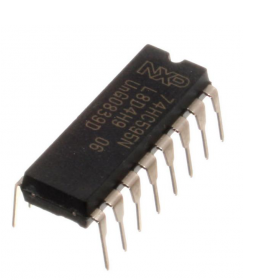
74HC595 chip*1
REV4 board *1
Red M5 LED*4
Green M5 LED*4
220Ω resistor*8
Breadboard*1
USB cable *1
Breadboard jumper wires*several
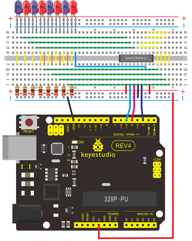
3. Circuit Connection Note: for pin 13 OE port of 74HC595, it needs to connect to GND.
Connection for REV4
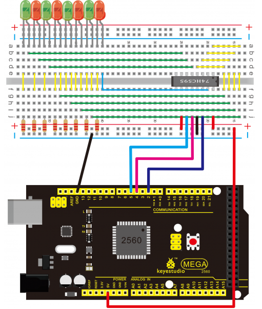
Connection for 2560 R3
The circuit may seem complicated, but soon you will find it easy!
4. Sample Code
int data = 2;// set pin 14 of 74HC595as data input pin SI
int clock = 5;// set pin 11 of 74hc595 as clock pin SCK
int latch = 4;// set pin 12 of 74hc595 as output latch RCK
int ledState = 0;
const int ON = HIGH;
const int OFF = LOW;

void setup()
{
    pinMode(data, OUTPUT);
    pinMode(clock, OUTPUT);
    pinMode(latch, OUTPUT);
}

void loop()
{
    for(int i = 0; i < 256; i++)
    {
        updateLEDs(i);
        delay(500);
    }
}

void updateLEDs(int value)
{
    digitalWrite(latch, LOW);//
    shiftOut(data, clock, MSBFIRST, ~value);// serial data “output”, high level first
    digitalWrite(latch, HIGH);// latch
}
5. Result After downloading the program, you can see 8 LEDs display 8-bit binary number.