5.10 Auto-Irrigation System
5.10.1 Water Pumping System
In this experiment, we use ESP32 development board to turn on/off the water pump by a relay module. A pump lifts water and transports liquids, and usually is combined with a relay module in usage.
Relay Module:
In usage, it is often used in the management of high voltage and load current, say, motors, high-currentsensors and high-powerlight.
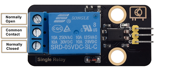
Normally Open (NO): This pin is normally open, unless a signal is received by the signal pin of the relay. Therefore, common pins are disconnected via NC pin and connected through NO pin.
Common Contact (COM): This pin connects to other modules, for example, water pump.
Normally Closed (NC): NC pin is linked with COM pin to form a closed circuit. It uses ESP32 board to control the closure and the disconnection of the relay module.

Water Pump:
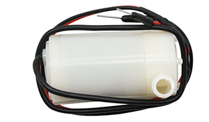
Parameters:
Power voltage: 5V
Static current: 2mA
Maximum contact voltage: 250VAC/30VDC
Maximum current: 10A
Open the 5.10.1Water-Pump code with Arduino IDE.
#define RelayPin 25
char content;  //Define a character string as the received value from serial port

void setup() {
  Serial.begin(9600);
  pinMode(RelayPin,OUTPUT);
}

void loop() {
  //Serial.read() receives one byte once. For example, when input "aaa", it receives one "a" at a time for three times in total.
  if(Serial.available() > 0) {
    if (Serial.read() == 'a') //When the input value equals to "a", irrigation begins.
    {
      digitalWrite(RelayPin,HIGH);
      delay(400);//irrigation delay
      digitalWrite(RelayPin,LOW);
      delay(700);
    }
  }
}
Choose the ESP32 Dev Module board and COM port, and upload the code.

Test Result:
Open the serial monitor and input “a”, pump water once.
Pay attention: Do not overflow water from plastic pools in experiments. Spilling water on other sensors may cause not only a short circuit or modulesto be out of work but also heat generation and even explosion. Do be extra careful! Especially for younger users, please operate with your parents.
5.10.2 Auto-Irrigation System
In this experiment, we connect the two sensors on ESP32 development board and program to read their output valuesto controlthe relay and water pump.
If the soil is very dry, the relay will turn on to control the water pump to irrigate plants; And if the waterlevel istoo low, the water pump will not be able to work, and the buzzer will alarm.
Open the 5.10.2Auto-irrigation code with Arduino IDE.
#include <LiquidCrystal_I2C.h>

#define BuzzerPin 16
#define SoilHumidityPin 32
#define WaterLevelPin 33
#define RelayPin 25
#define ButtonPin 5  //Define a button pin
int value = 0;       //Set an initial button value

LiquidCrystal_I2C lcd(0x27, 16, 2);

void setup() {
  //Set the pins mode
  pinMode(SoilHumidityPin, INPUT);
  pinMode(WaterLevelPin, INPUT);
  pinMode(RelayPin, OUTPUT);
  pinMode(ButtonPin, INPUT);

  //Initialize LCD
  lcd.init();
  //Turn on LCD backlight
  lcd.backlight();
  //Clear LCD displays
  lcd.clear();

  ledcAttachChannel(BuzzerPin, 1000, 8, 4);
}

void loop() {
  //define variables as the read values of water level, humidity and button state
  int shvalue = analogRead(SoilHumidityPin);
  int wlvalue = analogRead(WaterLevelPin);
  int ReadValue = digitalRead(ButtonPin);

  //Set the display position of cursor
  lcd.setCursor(0, 0);
  //Set the display position of character strings
  lcd.print("SoilHum:");
  lcd.setCursor(9, 0);
  lcd.print(shvalue);
  lcd.setCursor(0, 1);
  lcd.print("WaterLevel:");
  lcd.setCursor(11, 1);
  lcd.print(wlvalue);

  //Determine whether the button is pressed
  if (ReadValue == 0) {
    //Eliminate the button shake
    delay(10);
    if (ReadValue == 0) {
      value = !value;
      Serial.print("The current status of the button is : ");
      Serial.println(value);
    }
    //Again, determine whether the button is still pressed
    //Pressed: execute the loop; Released: exit the loop to next execution
    while (digitalRead(ButtonPin) == 0)
      ;
  }
  //When the detected humidity is lower than the set threshold, the buzzer starts to alarm. Press button to stop alarming.
  if (500 >= shvalue && value == 0) {
    ledcWriteTone(BuzzerPin, 532);
    delay(100);
    ledcWriteTone(BuzzerPin, 532);
    delay(100);
    ledcWriteTone(BuzzerPin, 659);
    delay(100);
    ledcWriteTone(BuzzerPin, 0);  //Stop alarming
  }
  //When the detected water level is lower than the set threshold, the buzzer starts to alarm. Press button to stop alarming.
  if (500 >= wlvalue && value == 0) {
    ledcWriteTone(BuzzerPin, 411);
    delay(100);
    ledcWriteTone(BuzzerPin, 639);
    delay(100);
    ledcWriteTone(BuzzerPin, 411);
    delay(100);
    ledcWriteTone(BuzzerPin, 0);  //Stop alarming
  }
  //When the detected humidity is lower than the set threshold, and the water is sufficient in the pool, irrigation starts automatically.
  if (500 >= shvalue && wlvalue >= 1000) {
    digitalWrite(RelayPin, HIGH);
    delay(400);  //Irrigation delay.
    digitalWrite(RelayPin, LOW);
    delay(700);
  }
  delay(500);
  //Clear displays
  lcd.clear();
}
Choose the ESP32 Dev Module board and COM port, and upload the code.
Test Result:
LCD 1602 will display the current value ofsoil humidity and waterlevel.

When the detected soil humidity value islower than 500, the buzzer alarms to notify that the soil is being arid. If the waterlevel value is greater than 1000, the irrigation starts automatically.
When the detected water level is lower than 500, the water pumping system doesn’t work, and the buzzer alarmsto notify that water is insufficient. Press the button to stop alarming.
