5.11 Web-controlled Smart Farm
5.11.0 Connect the ESP32 Board to the Network
ESP32 board is equipped with Wi-Fi(2.4G) and Bluetooth(4.2), which enable it to easily connect to WiFi and communicate with other devices on the network.
What do you need to prepare:
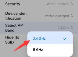
-A 2.4 GHz WiFi(It can be a mobile hotspot or a router)
-The WIFI name and password
-A phone/IPAD/computerthat can connect to the same WiFi.
Arduino IDE provides you wih library file <WiFi.h>, which support Wi-Fi configurations and ESP32 Wi-Fi networking monitoring.
A.Base station mode (STA or Wi-Fi client-side mode): In this mode, ESP32 connects to the Wi-Fi hotspot (AP).
B. AP mode (Soft-AP or Wi-Fi hotspot mode): In this mode, other Wi-Fi devices connect to ESP32.
C. AP-STA mode: In this mode, ESP32 is a Wi-Fi hotspot as well as a Wi-Fi device connecting to another Wi-Fi hotspot.
D. These modes is compatible with multiple safe modes, like WPA, WPA2 and WEP.
E. It is able to scan for Wi-Fi hotspot, including active and passive scan.
F. It supports promiscuous mode to monitor IEEE802.11 Wi-Fi Packets.
For wifi details, please refer to:
https://docs.espressif.com/projects/esp-idf/en/latest/esp32/api-reference/network/esp_wifi.html
ESPRESSIF official website: https://www.espressif.com.cn/en/home
Open the 5.11.0Connect-the-ESP32-to-the-Network code with Arduino IDE.
#include <WiFi.h>

const char* ssid = "your_SSID";
const char* password = "your_PASSWORD";

void setup() {
  Serial.begin(9600);
  //Initialize Wifi
  WiFi.begin(ssid, password);
  //Scan for wifi. If connection fails, stay in connecting, and execute "while" loop
  while (WiFi.status() != WL_CONNECTED) {
    delay(1000);
    Serial.println("Connecting to WiFi...");
  }
  //Connected. Print the IP address
  Serial.println("Connected to WiFi");
  Serial.println(WiFi.localIP());
}

void loop() {
}
Change your_SSID in the code to the name of your wifi, and your_PASSWORD to the wifi password
const char* ssid = "your_SSID";
const char* password = "your_PASSWORD";
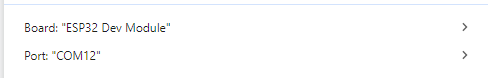
Choose the ESP32 Dev Module board and COM port, and upload the code.
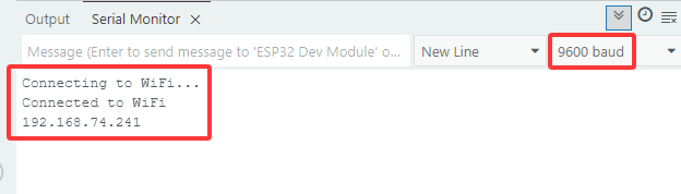
Test Result:
Upload the code, and the board will connect to Wi-Fi network and print the IP Address on the serial monitor.
5.11.1 Set Up a Website-HELLOWORLD
As long as connecting to Wi-Fi, Web server library of ESP32 is able to provide web pages. In the following example code, we set up a simple website to show “Hello, World!”.
Open the 5.11.1WiFi-HTML-HELLOWORLD code with Arduino IDE.
#include <WiFi.h>
#include <WebServer.h>

const char* ssid = "your_SSID";
const char* password = "your_PASSWORD";

WebServer server(80); //Set the server port to 80. Enter the website by IP address rather than the port number.

//Initialize the website
void handleRoot() {
  //Used to send HTTP to the client-side for response, sending 200 means success.
  server.send(200, "text/html", "<h1>Hello, World!</h1>");
}

void setup() {
  Serial.begin(9600);
  //Initialize wifi
  WiFi.begin(ssid, password);
  //Scan for wifi. If connection fails, stay in connecting, and execute "while" loop
  while (WiFi.status() != WL_CONNECTED) {
    delay(1000);
    Serial.println("Connecting to WiFi...");
  }

  //Connected. Print the IP address
  Serial.println("Connected to WiFi");
  Serial.println(WiFi.localIP());

  server.on("/", handleRoot);
  //Start server
  server.begin();
  Serial.println("Web server started");
}

void loop() {
  server.handleClient();
}
Change your_SSID in the code to the name of your wifi, and your_PASSWORD to the wifi password. Then upload the code.
const char* ssid = "your_SSID";
const char* password = "your_PASSWORD";
Choose the ESP32 Dev Module board and COM port, and upload the code.
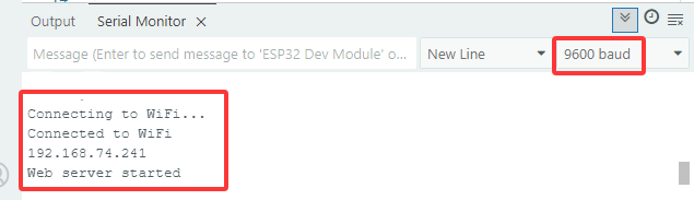
Test Result:
In this example code, we establish a Web server by WebServer library on ESP32. The function handleRoot() asks for processing in root path and sends HTML response of “Hello, World!” to client-side. Then,setup()setsthe rootroute, and server.begin()startsthe Web server.
Click on the serial monitorto view the IP address:
NOTE: When PC, mobile phones and ESP32 board are connected to one network, you can visit this website at PC and phones at the same time.
Accessthe IP in the PC browser or phone browser:
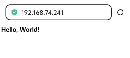
Note: Requires 2.4 GHz WIFI, not 5G The PC or mobile phone accessing the IP address needs to be connected to the same WIFI asthe ESP32 board.
5.11.2 Web-controlled smart farm

Open the 5.11.2WiFi-HTML-Smart-Farm code with Arduino IDE.
#include <Arduino.h>
#include <WiFi.h>
#include <WebServer.h>
#include <LiquidCrystal_I2C.h>
#include <dht11.h>
#include <ESP32Servo.h>

// Pin Definitions
#define DHT11PIN        17  // Temperature and humidity sensor pin
#define LEDPIN          27  // LED pin
#define SERVOPIN        26  // Servo pin
#define FANPIN1         19  // Fan IN+ pin
#define FANPIN2         18  // Fan IN- pin
#define STEAMPIN        35  // Steam sensor pin
#define LIGHTPIN        34  // Photoresistor pin
#define SOILHUMIDITYPIN 32  // Soil humidity sensor pin
#define WATERLEVELPIN   33  // Water level sensor pin
#define RELAYPIN        25  // Relay pin

// Initialize sensors and components
dht11 DHT11;
LiquidCrystal_I2C lcd(0x27, 16, 2);
Servo myservo;  // Servo object to control the servo

// WiFi credentials
const char *SSID = "your_SSID";
const char *PASS = "your_PASSWORD";

// Create WebServer object
WebServer server(80);

// Variables for controlling states
static int A = 0;
static int B = 0;
static int C = 0;

// HTML Web page content
const char index_html[] PROGMEM = R"rawliteral(
<!DOCTYPE HTML>
<html>
<title>TEST HTML ESP32</title>
<head>
  <meta charset="utf-8">
  <style>
    html, body {
      margin: 0;
      width: 100%;
      height: 100%;
      display: flex;
      justify-content: center;
      align-items: center;
      flex-direction: column;
      background-color: #f0f0f0;
    }

    /* The main button container */
    .btn {
      display: flex;
      justify-content: center;  /* Center the buttons */
      gap: 10px;  /* Add space between buttons */
      width: 320px;  /* Set width to ensure buttons are tightly packed */
      flex-wrap: wrap; /* Allow buttons to wrap to new lines if needed */
      margin-bottom: 20px;  /* Space between buttons and data display */
    }

    /* Button style */
    .btn button {
      width: 70px;  /* Set width for buttons */
      height: 70px;  /* Set height for buttons */
      border: none;
      font-size: 16px;
      color: #fff;
      background-color: #89e689;
      cursor: pointer;
    }

    .btn button:active {
      top: 2px;
    }

    /* The data display area */
    #dht {
      text-align: center;  /* Center the text */
      width: 320px;  /* Same width as the button container */
      color: #fff;
      background-color: #47a047;
      font-size: 18px; /* Adjust font size for readability */
      padding: 10px;
      border-radius: 10px;  /* Rounded corners */
      box-sizing: border-box;
      margin-bottom: 10px; /* Add space between the data display and buttons */
    }

  </style>
</head>
<body>

  <!-- Display area for sensor data -->
  <div id="dht"></div>

  <!-- Button row -->
  <div class="btn">
    <button id="btn-led" onclick="setLED()">LED</button>
    <button id="btn-fan" onclick="setFan()">Fan</button>
    <button id="btn-feeding" onclick="setFeeding()">Feeding</button>
    <button id="btn-watering" onclick="setWatering()">Watering</button>
  </div>

  <script>
    function setLED() {
      var payload = "A";
      var xhr = new XMLHttpRequest();
      xhr.open("GET", "/set?value=" + payload, true);
      xhr.send();
    }
    function setFan() {
      var payload = "B";
      var xhr = new XMLHttpRequest();
      xhr.open("GET", "/set?value=" + payload, true);
      xhr.send();
    }
    function setFeeding() {
      var payload = "C";
      var xhr = new XMLHttpRequest();
      xhr.open("GET", "/set?value=" + payload, true);
      xhr.send();
    }
    function setWatering() {
      var payload = "D";
      var xhr = new XMLHttpRequest();
      xhr.open("GET", "/set?value=" + payload, true);
      xhr.send();
    }

    setInterval(function () {
      var xhttp = new XMLHttpRequest();
      xhttp.onreadystatechange = function () {
        if (this.readyState == 4 && this.status == 200) {
          document.getElementById("dht").innerHTML = this.responseText;
        }
      };
      xhttp.open("GET", "/dht", true);
      xhttp.send();
    }, 1000)
  </script>

</body>
</html>

)rawliteral";

// Function to merge sensor data into HTML format
String Merge_Data(void) {
  String dataBuffer;
  String Humidity;
  String Temperature;
  String Steam;
  String Light;
  String SoilHumidity;
  String WaterLevel;

  // Read DHT11 sensor
  int chk = DHT11.read(DHT11PIN);

  // Read other sensors
  Steam = String(analogRead(STEAMPIN) / 4095.0 * 100);
  Light = String(analogRead(LIGHTPIN));
  int shvalue = analogRead(SOILHUMIDITYPIN) / 4095.0 * 100 * 2.3;
  shvalue = shvalue > 100 ? 100 : shvalue;
  SoilHumidity = String(shvalue);
  int wlvalue = analogRead(WATERLEVELPIN) / 4095.0 * 100 * 2.5;
  wlvalue = wlvalue > 100 ? 100 : wlvalue;
  WaterLevel = String(wlvalue);
  Temperature = String(DHT11.temperature);
  Humidity = String(DHT11.humidity);

  // Construct HTML content
  dataBuffer += "<p>";
  dataBuffer += "<h1>Sensor Data</h1>";
  dataBuffer += "<b>Temperature:</b><b>" + Temperature + "</b><b>℃</b><br/>";
  dataBuffer += "<b>Humidity:</b><b>" + Humidity + "</b><b>%rh</b><br/>";
  dataBuffer += "<b>WaterLevel:</b><b>" + WaterLevel + "</b><b>%</b><br/>";
  dataBuffer += "<b>Steam:</b><b>" + Steam + "</b><b>%</b><br/>";
  dataBuffer += "<b>Light:</b><b>" + Light + "</b><br/>";
  dataBuffer += "<b>SoilHumidity:</b><b>" + SoilHumidity + "</b><b>%</b><br/>";
  dataBuffer += "</p>";

  return dataBuffer;
}

// Configure actions based on received HTTP requests
void Config_Callback() {
  if (server.hasArg("value")) {
    String HTTP_Payload = server.arg("value");
    Serial.printf("[%lu]%s\r\n", millis(), HTTP_Payload.c_str());

    if (HTTP_Payload == "A") {
      if (A) {
        digitalWrite(LEDPIN, LOW);
        A = 0;
      } else {
        digitalWrite(LEDPIN, HIGH);
        A = 1;
      }
    }

    if (HTTP_Payload == "B") {
      if (B) {
        digitalWrite(FANPIN1, LOW);
        digitalWrite(FANPIN2, LOW);
        B = 0;
      } else {
        delay(500);
        digitalWrite(FANPIN1, HIGH);
        digitalWrite(FANPIN2, LOW);
        delay(500);
        B = 1;
      }
    }

    if (HTTP_Payload == "C") {
      if (C) {
        myservo.write(80);
        delay(500);
        C = 0;
      } else {
        C = 1;
        myservo.write(180);
        delay(500);
      }
    }

    if (HTTP_Payload == "D") {
      digitalWrite(RELAYPIN, HIGH);
      delay(400);
      digitalWrite(RELAYPIN, LOW);
      delay(650);
    }
  }
  server.send(200, "text/plain", "OK");
}

// Handle invalid URL access
void notFound() {
  server.send(404, "text/plain", "Not found");
}

void setup() {
  Serial.begin(9600);

  // Connect to WiFi
  WiFi.begin(SSID, PASS);
  while (!WiFi.isConnected()) {
    delay(500);
    Serial.print(".");
  }
  Serial.println("WiFi connected.");
  Serial.println("IP address: ");
  Serial.println(WiFi.localIP());

  // Set up pins
  pinMode(LEDPIN, OUTPUT);
  pinMode(STEAMPIN, INPUT);
  pinMode(LIGHTPIN, INPUT);
  pinMode(SOILHUMIDITYPIN, INPUT);
  pinMode(WATERLEVELPIN, INPUT);
  pinMode(RELAYPIN, OUTPUT);
  pinMode(FANPIN1, OUTPUT);
  pinMode(FANPIN2, OUTPUT);

  delay(1000);

  // Attach servo to the pin
  myservo.attach(SERVOPIN);
  myservo.write(180);

  // Initialize LCD
  lcd.init();
  lcd.backlight();
  lcd.clear();
  lcd.setCursor(0, 0);
  lcd.print("IP:");
  lcd.setCursor(0, 1);
  lcd.print(WiFi.localIP());

  // Set up server routes
  server.on("/", HTTP_GET, []() {
    server.send(200, "text/html", index_html);
  });

  server.on("/dht", HTTP_GET, []() {
    server.send(200, "text/plain", Merge_Data().c_str());
  });

  server.on("/set", HTTP_GET, Config_Callback);
  server.onNotFound(notFound);

  // Start the server
  server.begin();
}

void loop() {
  server.handleClient();
}
Change your_SSID in the code to the name of your wifi, and your_PASSWORD to the wifi password. Then upload the code.
const char* ssid = "your_SSID";
const char* password = "your_PASSWORD";
Choose the ESP32 Dev Module board and COM port, and upload the code.
Test Result:
NOTE: When PC, mobile phones and ESP32 board are connected to one network, you can visit this website at PC and phones at the same time.
View IP address from LCD1602:
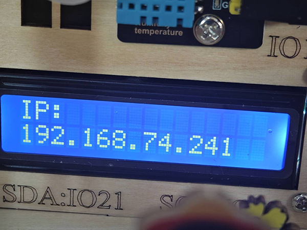
Input the IP addressin browsers at mobile phones or PC, you can see the sensor values at the top of the page and controlthe LED, fan, feeding cabin and water pump with the buttons below.

Note: Requires 2.4 GHz WIFI, not 5G The PC or mobile phone accessing the IP address needs to be connected to the same WIFI asthe ESP32 board.