Project 1: LED Blinks
(1)Description:
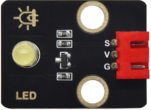
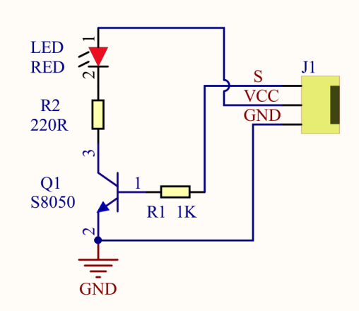
For starters and enthusiasts, LED Blink is a fundamental program. LED, the abbreviation of light emitting diodes, consists of Ga, As, P, N chemical compounds and so on. The LED can flash in diverse colors by altering the delay time in the test code. When in control, power on GND and VCC. The LED will be on if the S end is at a high level; otherwise, it will go off.
(2)Parameters:

Control interface: digital port
Working voltage: DC 3.3-5V
Pin spacing: 2.54mm
LED display color: yellow
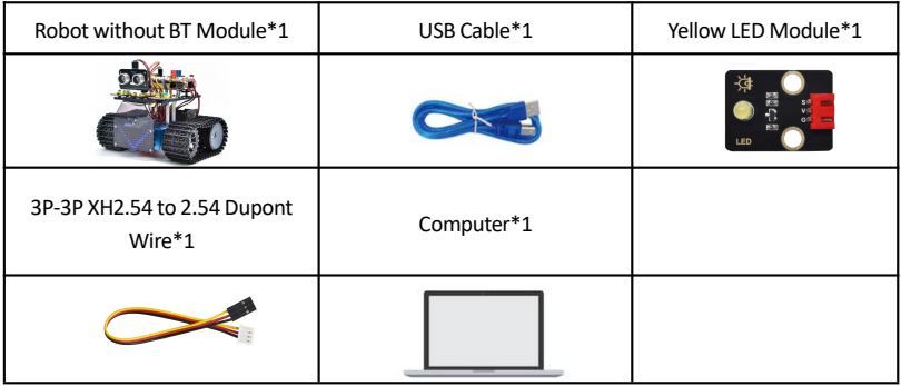
(3)Components Required:
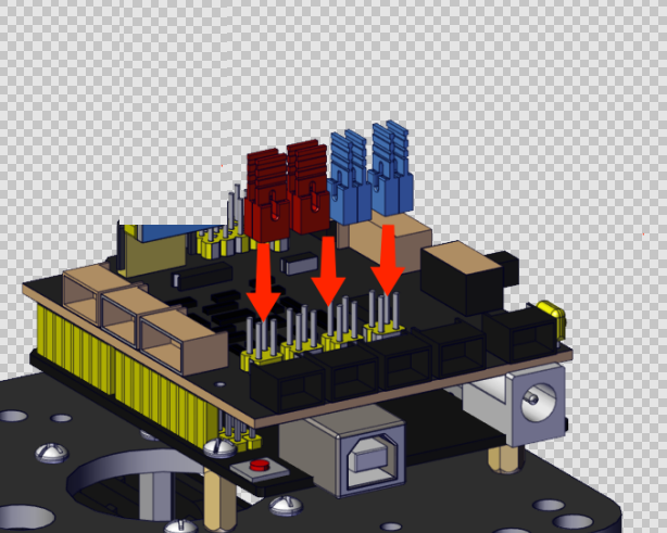
(4)8833 Motor Driver Expansion Board:
The Keyestudio 8833 motor driver expansion board is compatible with the Arduino UNO development board. Just stack it onto the development board when using it.
(5)Connection Diagram:
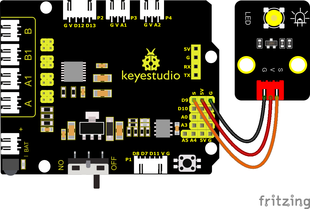
NOTE: The LED is connected to the D9 port. Remember to install jumper caps onto the shield.
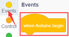
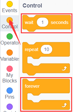
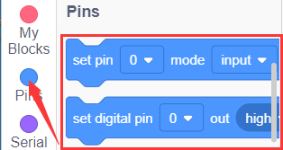
(6)Test Code:
You can also drag blocks to edit your code, as shown below.
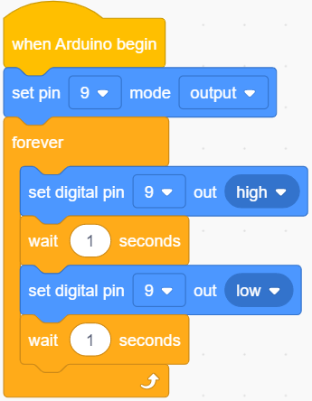
Complete Test Code
(Note: Do not connect the Bluetooth module before uploading the code, because uploading the code also uses serial communication, and there may be conflicts with the Bluetooth serial communication, which can cause the upload to fail.)
(7)Test Results:
Upload the program, LED blinks at the interval of 1s.
(8)Extension Practice:
We have known how to control the LED, then let’s change the frequency of the LED.
We can the frequency of the LED without changing the pin of the LED. Let’s modify the code.
You can also drag blocks to edit your code, as shown below.
Complete Test Code
(Note: Do not connect the Bluetooth module before uploading the code, because uploading the code also uses serial communication, and there may be conflicts with the Bluetooth serial communication, which can cause the upload to fail.)
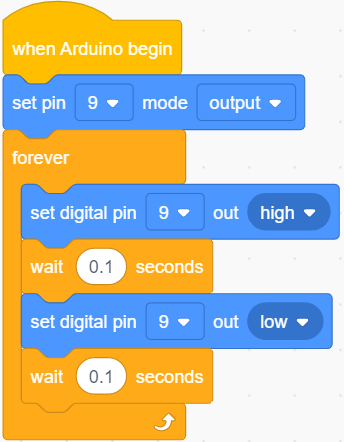
The test result shows that the LED flashes faster. Therefore, we can draw a conclusion that pins and time delaying affect flash frequency.