Project 9: 8*16 Facial Expression LED Dot Matrix
(1)Description:
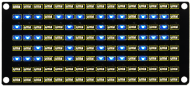
Won’t it be fun if a expression board is added to the robot? And the Keyestudio 8*16 LED dot matrix can do the trick. With the help of it, you could design facial expressions, images, patterns and other displays by yourselves.
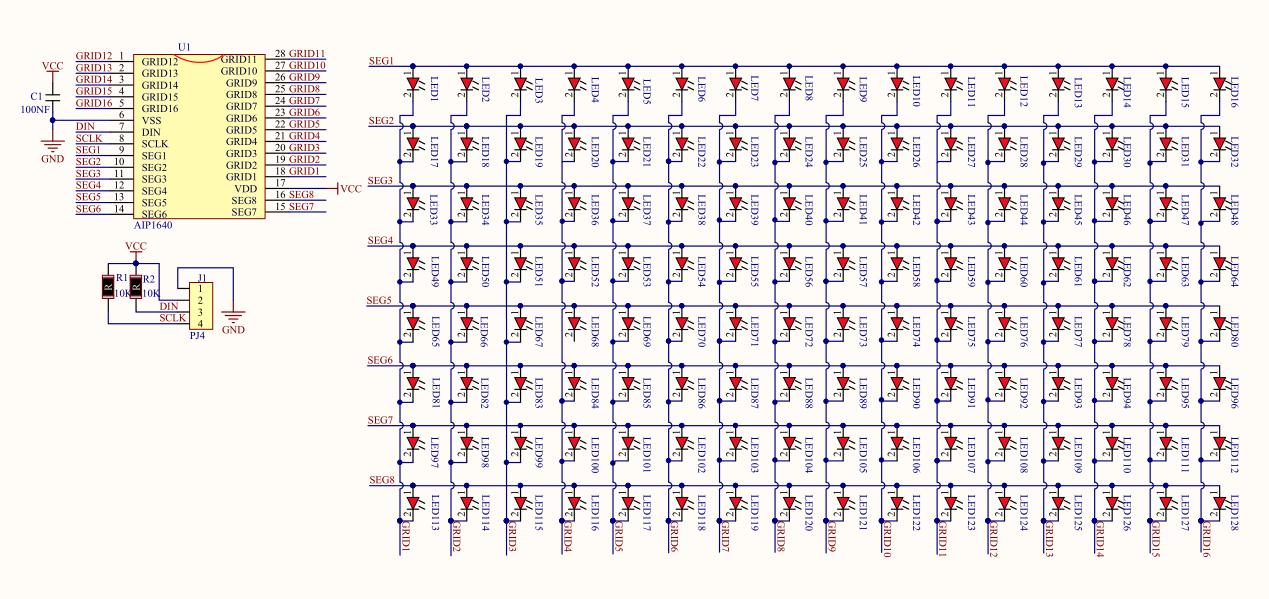
The 8*16 LED board comes with 128 LEDs. The data of the microprocessor (Arduino) communicates with the AiP1640 through a two-wire bus interface. Therefore, it can control the on and off of 128 LEDs on the module, so as to make the dot matrix on the module to display the pattern you need. A HX-2.54 4Pin cable is provided for your convenience of wiring.
(2)Parameters:
Working voltage: DC 3.3-5V
Power loss: 400mW
Oscillation frequency: 450KHz
Drive current: 200mA
Working temperature: -40~80℃
Communication mode: two-wire bus
(3)Knowledge:
Circuit of the 8*16 LED dot matrix
Principle of the 8*16 LED dot matrix
How to control each LED of the 8*16 dot matrix? It is known that each byte has 8 bits and each bit is 0 or 1. when it is 0, LED is off while when it is 1 LED is on. One byte can control one column of the LED,and naturally 16 bytes can control 16 columns of LEDs, that’s the 8*16 dot matrix.
Pins description and communication protocol
The data of the microprocessor (Arduino) communicates with the AiP1640 through a two-wire bus cable.
The communication protocol diagram is as follows (SCLK) is SCL, (DIN) is SDA.
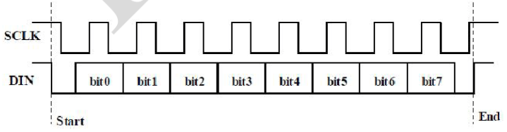
①The starting condition for data input: SCL is high level and SDA changes from high to low.
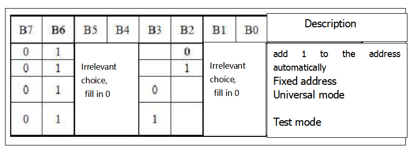
②For data command setting, there are methods as shown in the figure below.
In our sample program, select the way to add 1 to the address automatically, the binary value is 0100 0000 and the corresponding hexadecimal value is 0x40.
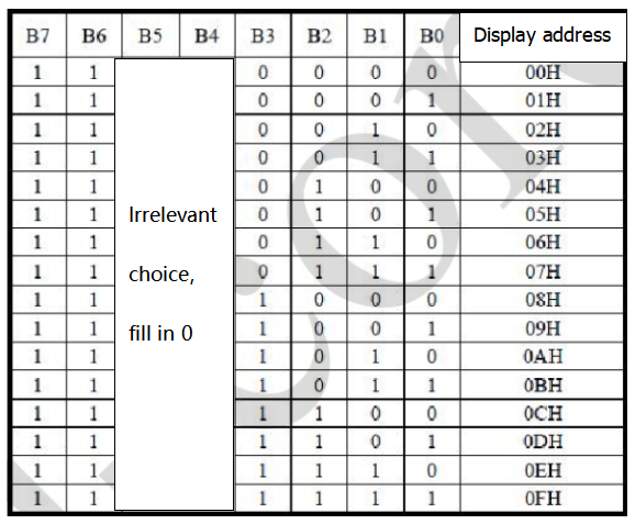
③For address command setting, the address can be selected as shown below.
The first 00H is selected in our sample program, and the binary number 1100 0000 corresponds to the hexadecimal 0xc0.
④The requirement for data input is that when SCL is at high level when inputting data, the signal on SDA must remain unchanged. Only when the clock signal on SCL is at low level, can the signal on SDA be changed. The input of data is the low bit first, and the high bit later.
⑤The condition for the end of data transmission is that when SCL is at low level, SDA at low level and SCL at high level, the level of SDA becomes high.
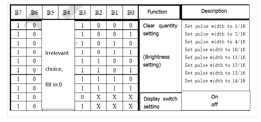
⑥Display control, set different pulse width, pulse width can be selected as shown in the figure below.
In the example, the pulse width is 4/16, and the hexadecimal corresponding to 1000 1010 is 0x8A.
Instructions for the use of modulus tool
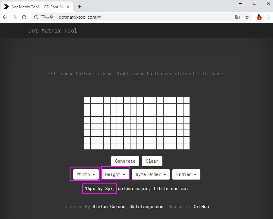
The dot matrix tool uses the online version, and the link is: http://dotmatrixtool.com/#
①Enter the link and the page appears as shown below
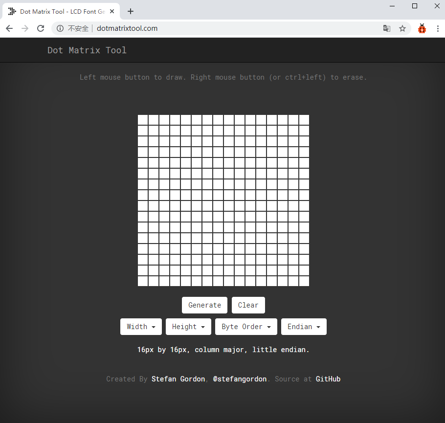
②The dot matrix is 8*16, so adjust the height to 8 and width to 16, as shown in the figure below.
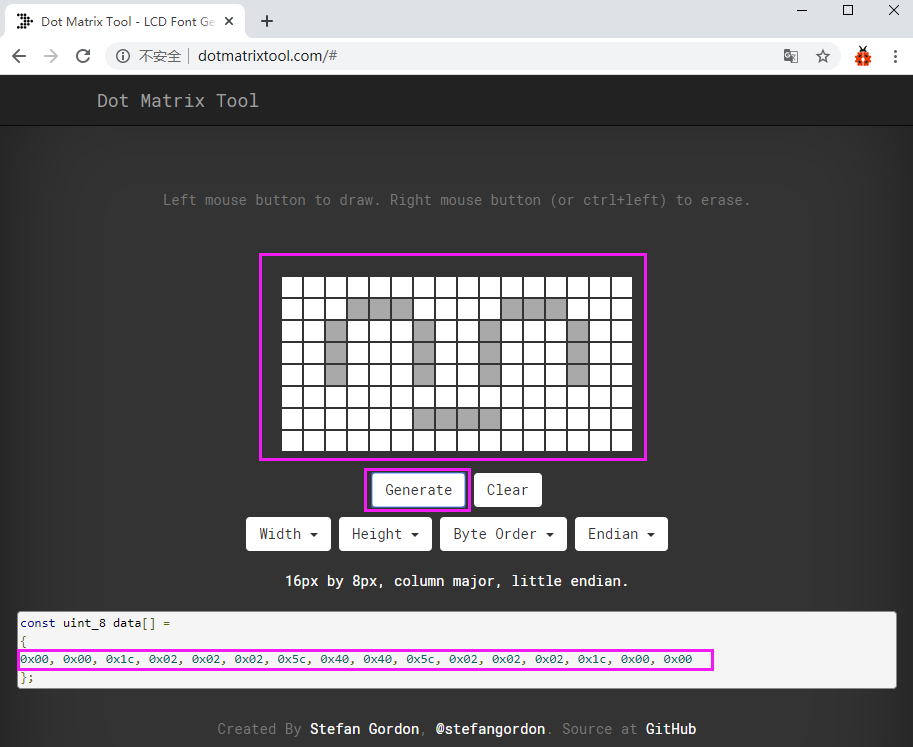
③Generate hexadecimal data from the pattern.
As shown in the figure below, press the left mouse button to select, right click to cancel; draw the pattern you want, click Generate, and the hexadecimal data we need will be generated.
(4)Connection Diagram:
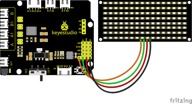
The GND, VCC, SDA, and SCL of the 8x16 LED light board are respectively connected to the G(GND), V (VCC), A4 and A5 of the expansion board for two-wire serial communication.
(Note: though it is connected with the IIC pin of Arduino, this module is not for IIC communication. And the IO port here is to simulate I2C communication and can be connected with any two pins )
(5)Test Code:
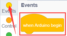
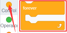
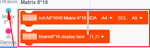
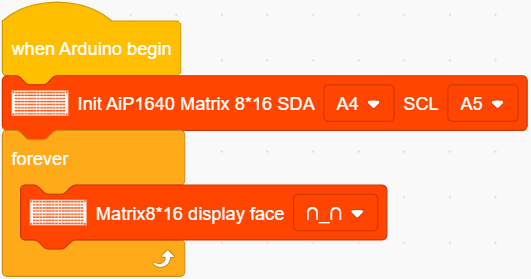
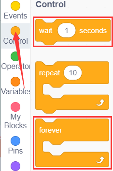
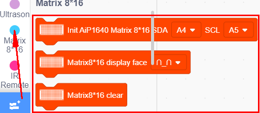
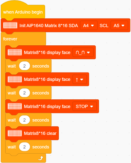
You can also drag blocks to edit your code, as shown below
Complete Test Code
(Note: Do not connect the Bluetooth module before uploading the code, because uploading the code also uses serial communication, and there may be conflicts with the Bluetooth serial communication, which can cause the upload to fail.)
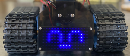
(6)Test Results:
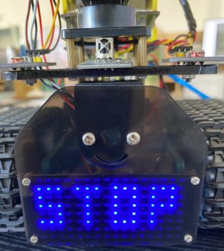
After uploading the test code successfully, wire up, turn the DIP switch to the ON end and power up, a smile-shaped pattern shows on the dot matrix.
(7)Extension Practice:
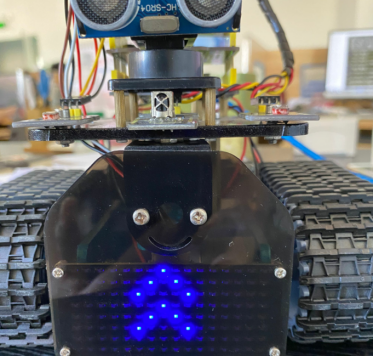
We use the modulus tool we just learned, http://dotmatrixtool.com/#, to make the dot matrix display the pattern start , go forward, and stop and then clear the pattern. The time interval is 2000 ms.
Block to show smile face
Code to show expression
Block to show heart
Code for moving forward
Block for going back
Block for turning left
Block for turning right
Block for stopping
Block for clearing up
You can also drag blocks to edit your code, as shown below.
(1)
(2)
(3)
Complete Test Code
(Note: Do not connect the Bluetooth module before uploading the code, because uploading the code also uses serial communication, and there may be conflicts with the Bluetooth serial communication, which can cause the upload to fail.)
Upload the code to the development board, the 8*16 board will show following patters.