Project 5: Servo Control
(1)Description:
A servo motor is a position control rotary actuator. It mainly consists of a housing, a circuit board, a core-less motor, a gear, and a position sensor. Its working principle is that the servo receives the signal sent by the MCU or receiver and produces a reference signal with a period of 20ms and a width of 1.5ms. It then compares the acquired DC bias voltage to the voltage of the potentiometer and obtains the voltage difference output.
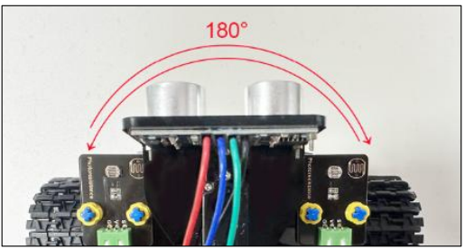
When the motor speed is constant, the potentiometer is driven to rotate through the cascade reduction gear, which leads that the voltage difference is 0, and the motor stops rotating. Generally, the angle range of servo rotation is 0° –180 °.
The rotation angle of servo motor is controlled by regulating the duty cycle of PWM (Pulse-Width Modulation) signal. The standard cycle of PWM signal is 20ms (50Hz). Theoretically, the width is distributed between 1ms-2ms, but in fact, it’s between 0.5ms-2.5ms. The width corresponds to the rotation angle from 0° to 180°. Note that for different brand motors, the same signal may result in different rotation angles.
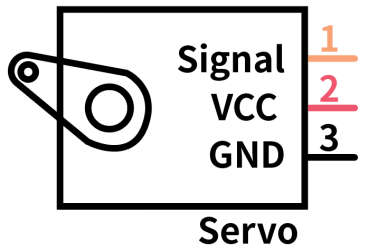
In general, servo has three lines in brown, red and orange. The brown wire is grounded, the red one is a positive pole line and the orange one is a signal line.
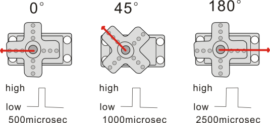
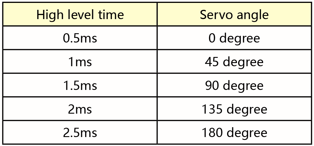
The angle of the servo:
(2)Parameters:
Working voltage: DC 4.8V ~ 6V
Operating angle range: about 180 ° (at 500 → 2500 μsec)
Pulse width range: 500 → 2500 μsec
No-load speed: 0.12 ± 0.01 sec / 60 (DC 4.8V) 0.1 ± 0.01 sec / 60 (DC 6V)
No-load current: 200 ± 20mA (DC 4.8V) 220 ± 20mA (DC 6V)
Stopping torque: 1.3 ± 0.01kg · cm (DC 4.8V) 1.5 ± 0.1kg · cm (DC 6V)
Stop current: ≦ 850mA (DC 4.8V) ≦ 1000mA (DC 6V)
Standby current: 3 ± 1mA (DC 4.8V) 4 ± 1mA (DC 6V)
(3)Connection Diagram:
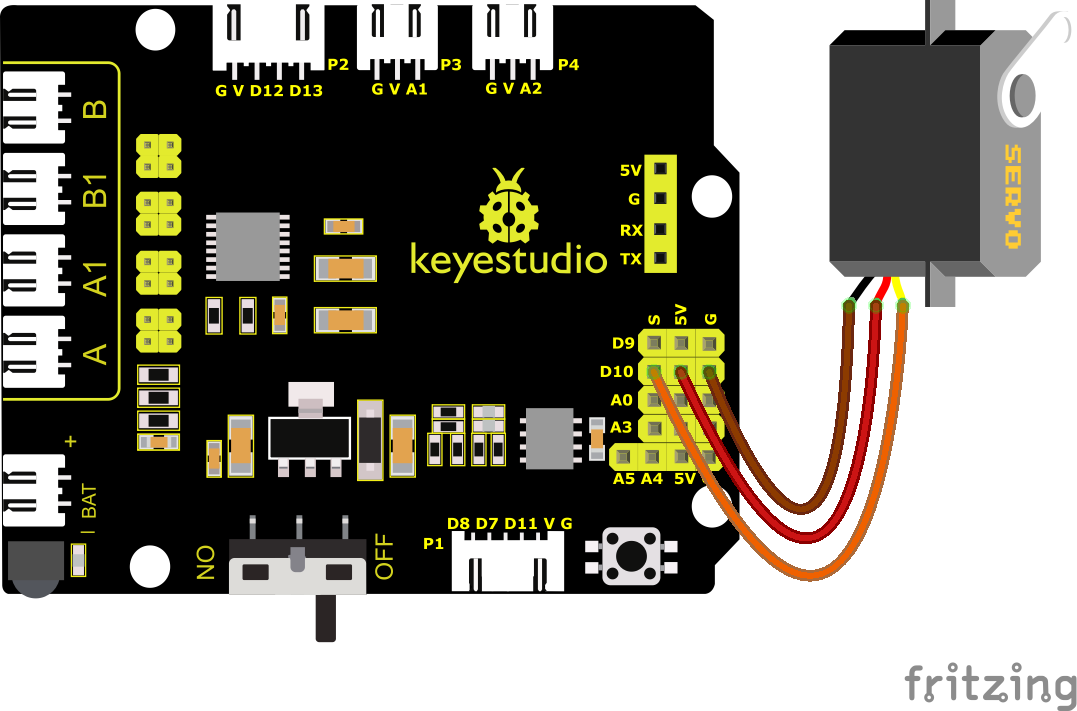
Note: The brown, red, and orange wires of the servo are respectively attached to Gnd(G), 5v(V), and D10 of the shield. Remember to connect an external power supply because of the high current of the servo. If not, the development board will be burnt out.
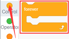
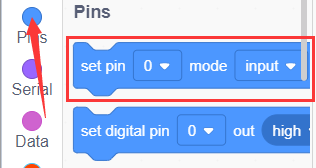
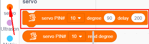
(4)Test Code:
You can also drag blocks to edit your code, as shown below

Complete Test Code
(Note: Do not connect the Bluetooth module before uploading the code, because uploading the code also uses serial communication, and there may be conflicts with the Bluetooth serial communication, which can cause the upload to fail.)
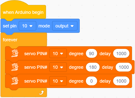
(6)Test Results:
Upload code, plug in power and servo moves in the range of 0° and 180°.