Project 15:Servo
1. Description
For those DIY smart cars, they often have the function of automatic obstacle avoidance. In the DIY process, we need to use a servo to control the ultrasonic module to rotate left and right, and then detect the distance between the car and the obstacle, so as to control the car to avoid the obstacle. If other microcontrollers are used to control the rotation of the servo, we need to set a certain frequency and a certain width of pulse to control the servo angle.
However, if the micro:bit main board is used to control the servo angle, we only need to set the control angle in the development environment where the corresponding pulse will be automatically set to control the servo rotation. In this project, you will learn how to control the servo to rotate back and forth between 0° and 90°.
2. Information of the Servo
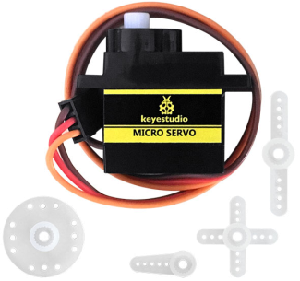
Servo motor is a position control rotary actuator. It mainly consists of housing, circuit board, core-less motor, gear and position sensor. Its working principle is that the servo receives the signal sent by MCU or receiver, and produces a reference signal with a period of 20ms and width of 1.5ms, then compares the acquired DC bias voltage to the voltage of the potentiometer and obtains the voltage difference output.
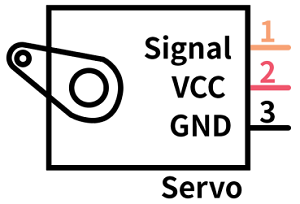
For the servo used in this project, the brown wire is the ground, the red one is the positive wire, and the orange one is the signal wire.
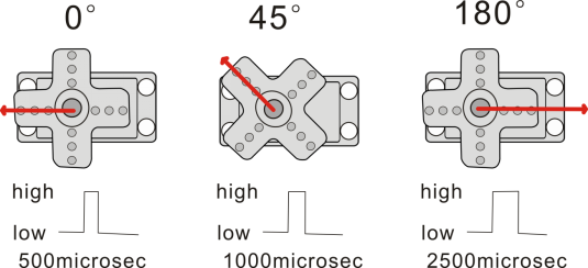
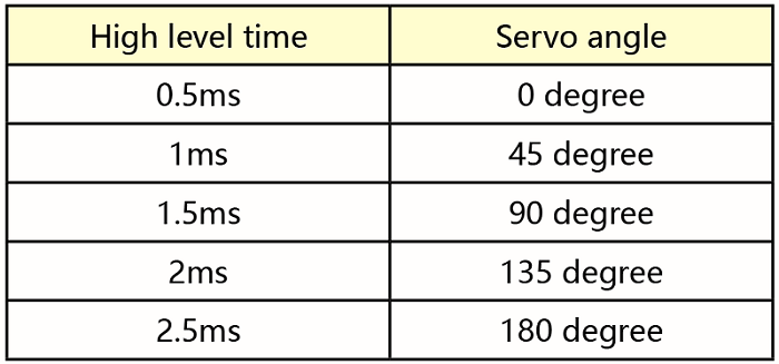
The rotation angle of servo motor is controlled by regulating the duty cycle of PWM (Pulse-Width Modulation) signal. The standard cycle of PWM signal is 20ms (50Hz). Theoretically, the width is distributed between 1ms-2ms, but in fact, it’s between 0.5ms-2.5ms. The width corresponds to the rotation angle from 0° to 180°. But note that for different brand motor, the same signal may have different rotation angle.
More details:
3. Parameters
Working voltage: DC 4.8V ~ 6V
Operating angle range: about 180 ° (at 500 → 2500 μsec)
Pulse width range: 500 → 2500 μsec
No-load speed: 0.12 ± 0.01 sec / 60 (DC 4.8V) 0.1 ± 0.01 sec / 60 (DC 6V)
No-load current: 200 ± 20mA (DC 4.8V) 220 ± 20mA (DC 6V)
Stopping torque: 1.3 ± 0.01kg · cm (DC 4.8V) 1.5 ± 0.1kg · cm (DC 6V)
Stop current: ≦ 850mA (DC 4.8V) ≦ 1000mA (DC 6V)
Standby current: 3 ± 1mA (DC 4.8V) 4 ± 1mA (DC 6V)
4. Preparation
Insert the micro:bit board into the slot of keyestudio 4WD Mecanum Robot Car V2.0
Place batteries into battery holder
Dial power switch to ON end
Connect the micro:bit to your computer via an USB cable
Open the Web version of Makecode
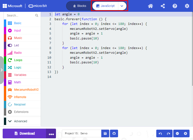
5. Test Code

Click“JavaScript” to view the corresponding JavaScript code:
Test Result
After uploading the test code and dial POWER switch to ON end, the servo rotates from 0 degree to 180 degrees.