Project 17:Line Tracking Sensor
Project 17.1:Detect Line Tracking Sensor
1. Description
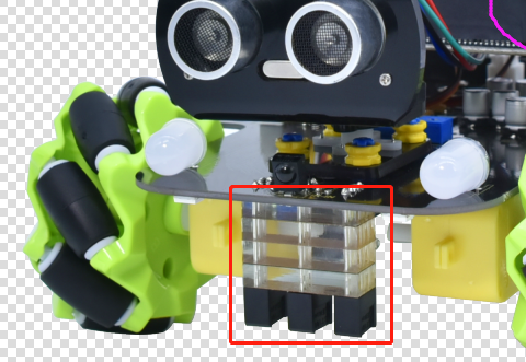
The motor driver board of the Keyestudio 4WD Mecanum Robot Car comes with a 3-channel line tracking sensor, which adopts TCRT5000 IR tubes and 3 potentiometers.
The TCRT5000 IR tube contains an IR emitting tube and an IR receiving tube. When the infrared signals of the emitting tube is received by the receiving tube through reflection, the resistance of the receiving tube will change, which is generally reflected in the voltage change on the circuit.
The resistance varies depending on the intensity of the infrared signals received by the receiving tube, which is often in the color of the reflecting surface and the distance of the reflecting surface receiving tube. At the time of detection, black is high level active and white is low level active.
2. Working Principle
When the car runs above a white road, the IR emitting tube installed under the car emits infrared signals to detect the road and the receiving tube will receive signals sending back. Then the output end outputs low level(0); when it detects black lines, it outputs high level(1).
After putting a white paper on the bottom of the 4WD Mecanum Robot Car, we will rotate the potentiometers on the 3-way tracking sensor. When the indicator light on the sensor module is on, pick up the car to make the two wheels on the 4WD Mecanum Robot Car separate. The height of the white paper is about 1.5cm, when the indicator light on the sensor module is off, and then the sensitivity is adjusted.
3. Preparation
Insert the micro:bit board into the slot of keyestudio 4WD Mecanum Robot Car V2.0
Place batteries into battery holder
Dial power switch to ON end
Connect the micro:bit to your computer via an USB cable
Open the Web version of Makecode
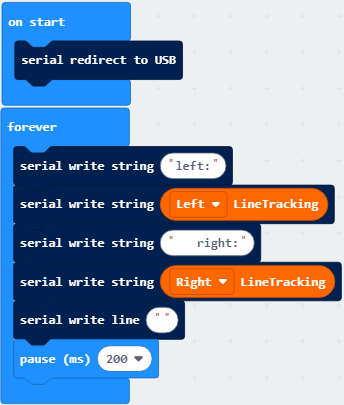
4. Test Code
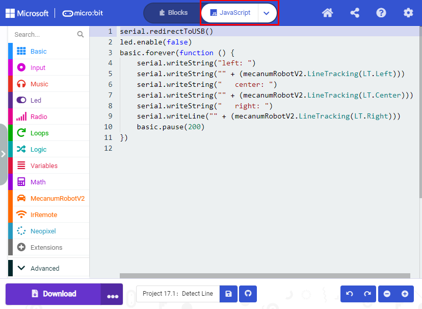
Click“JavaScript” to view the corresponding JavaScript code:
5. Test Result
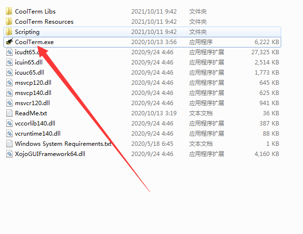
Download code to micro:bit board, dial POWER switch to ON end.
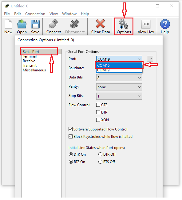
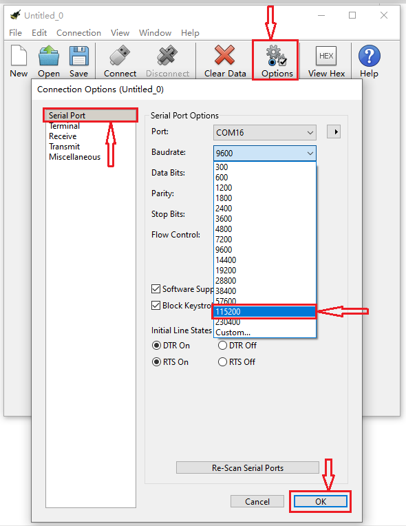
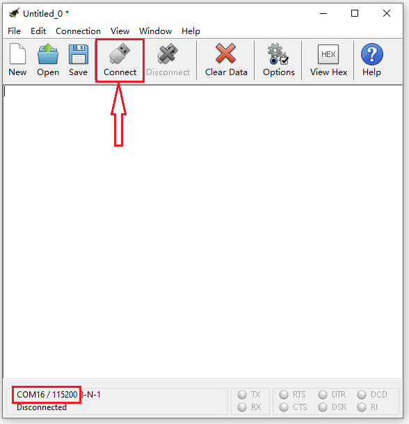
Open CoolTerm, click Options to select SerialPort. Set COM port and 115200 baud rate. Click“OK”and“Connect”.
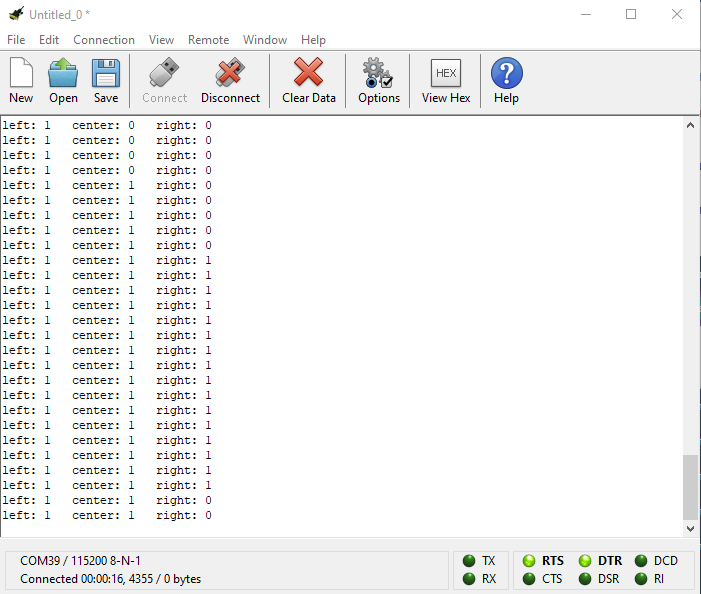
The CoolTerm serial monitor displays the digital signals read by the line tracking sensors.
Project 17.2:Tracking Smart Car
1. Description
In this lesson we will combine a line tracking sensor with a motor to make a line tracking smart car.
The micro:bit board will analyze the signals and control the smart car to show the line tracking function.
2. Working Principle
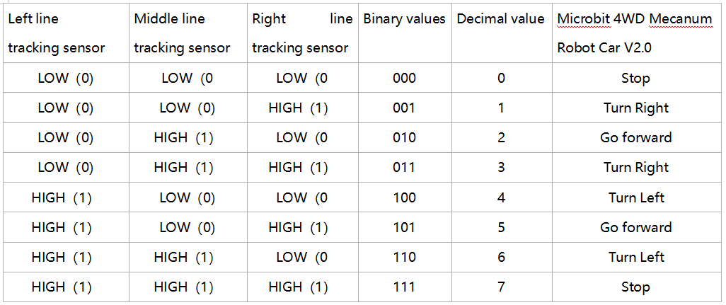
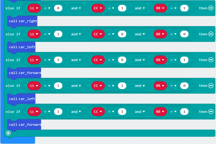
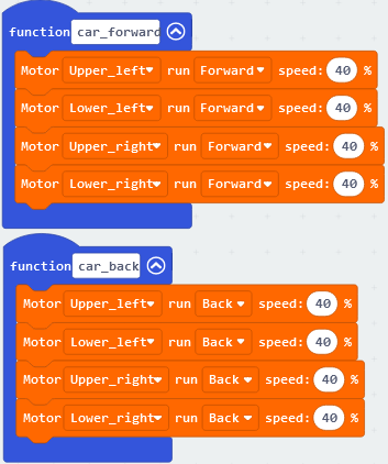
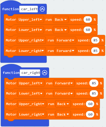
The smart car will make different moves according to the value received by the 3-channel line tracking sensor.
3. Preparation
Insert the micro:bit board into the slot of keyestudio 4WD Mecanum Robot Car V2.0
Place batteries into battery holder
Dial power switch to ON end
Connect the micro:bit to your computer via an USB cable
Open the Web version of Makecode
Warning: The 3-way tracking sensor should be used in environments without infrared interference such as sunlight. Sunlight contains a lot of invisible light, such as infrared and ultraviolet. In an environment with strong sunlight, the 3-way tracking sensor cannot work properly.
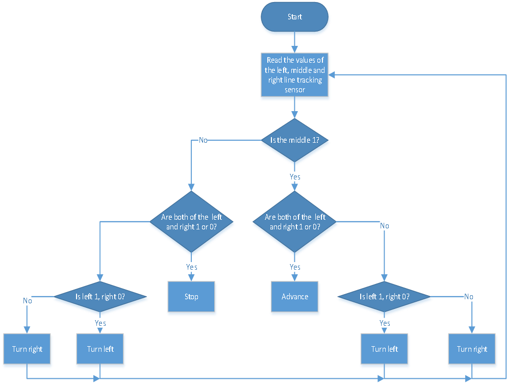
4.Flow Chart
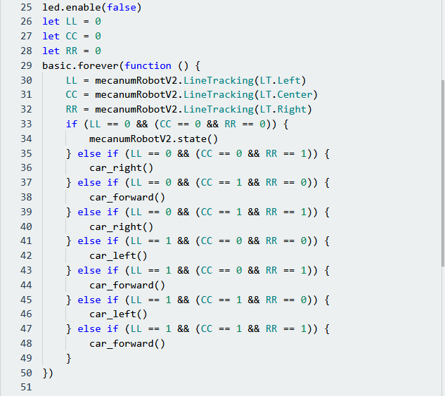
5. Test Code
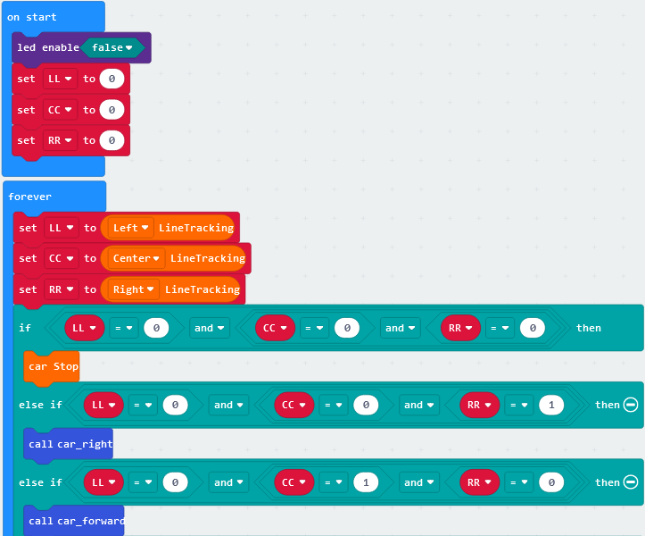
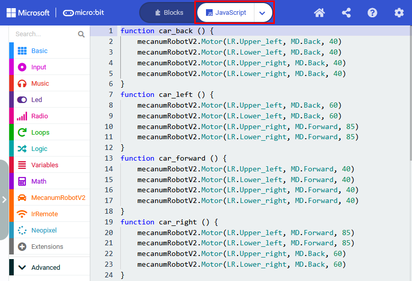
Click“JavaScript”to view the corresponding JavaScript code:
5. Test Result
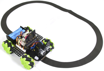
Download code to micro:bit and dial POWER to ON end, line tacking car goes forward along black line .
Note: turn on the switch at the back of micro:bit car, the width of black line should be larger than the width of line tracking sensor.
Avoid to test smart car under the strong light.