Project 1 LED Blink
1.Description
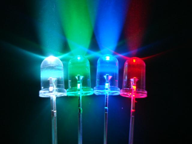
For starters and enthusiasts, LED Blink is a fundamental program. LED, the abbreviation of light emitting diodes, consists of Ga, As, P, N chemical compounds and so on.
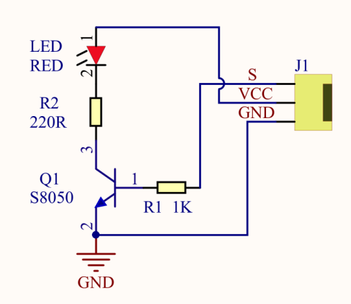
The LED can flash in diverse color by altering the delay time in the test code. When in control, power on GND and VCC, the LED will be on if S end is in high level, otherwise it will go off.
2.Specification
Control interface: digital port
Working voltage: DC 3.3-5V
Pin spacing: 2.54mm
LED display color: red
3.Components
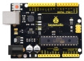
Development Board *1 |
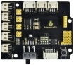
8833 Motor Driver *1 |
Red LED Module*1 |
|---|---|---|
|
|
|
3P F-F Dupont Wire*1 |
USB Cable*1 |
|
|
|


4.Wiring Diagram
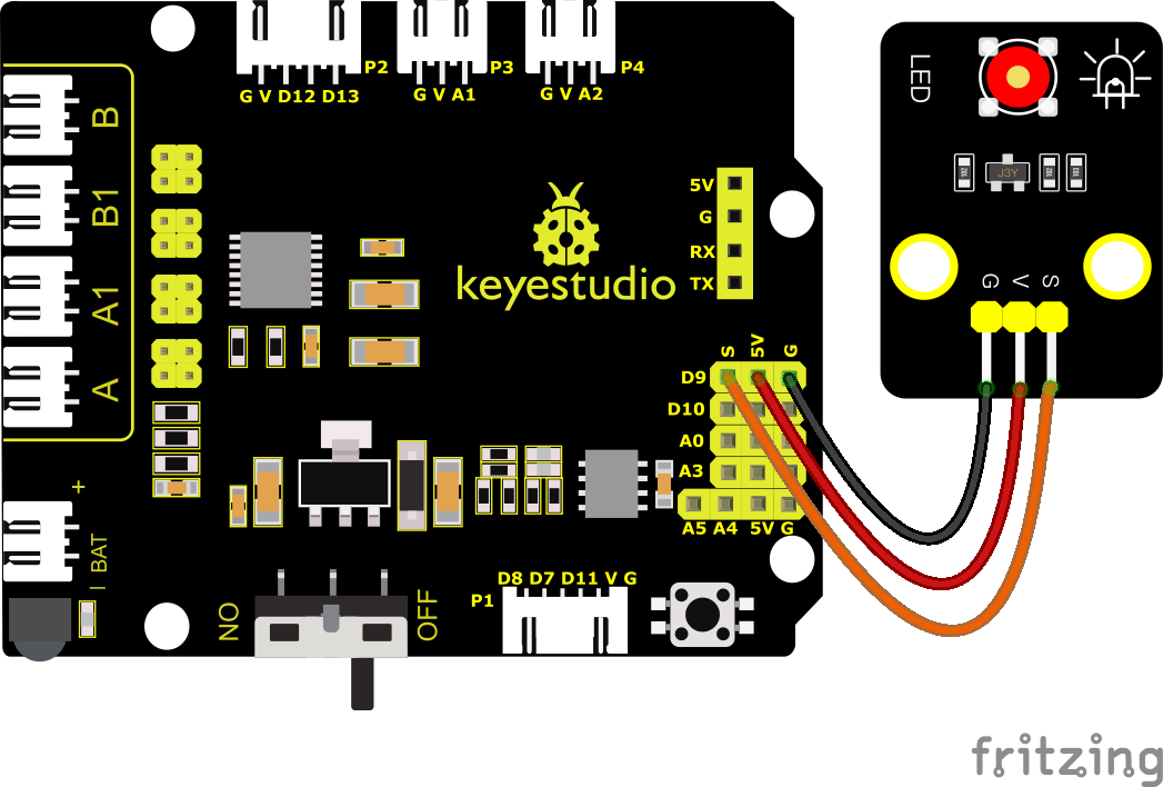
As can be seen from the above figure, the Keyestudio 8833 motor driver expansion board is stacked on the Keyestudio 4.0 development board.
The pin G, V and S of the LED module are connected to G, 5V and D9 of the expansion board respectively.
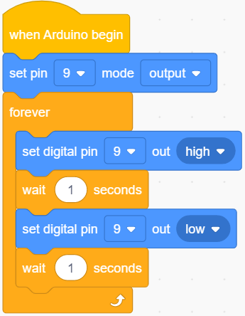
5.Test Code
You can drag blocks to edit. Blocks listed below are for your reference.
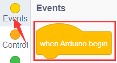
(1).
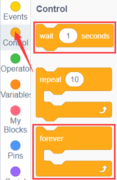
(2).
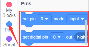
(3).
Complete Test Code
6.Test Result
After successfully uploading the code to the V4.0 board, connect the wirings according to the wiring diagram, and use a USB cable to connect the computer to power the board. After powering on, you will see the LED connected to the D9 will be on and off.
7.Extension Practice
Next, we look to change the frequency of LED flicker by changing the wait time.
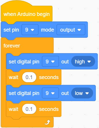
After successfully uploading the code to the V4.0 board, connect the wirings according to the wiring diagram, and use a USB cable to connect the computer to power the board. The test result shows that the LED flashes faster.