Project 4 Servo Control
1.Description
Servo motor is a position control rotary actuator. It mainly consists of a housing, a circuit board, a core-less motor, a gear and a position sensor. Its working principle is that the servo receives the signal sent by MCUs or receivers and produces a reference signal with a period of 20ms and width of 1.5ms, then compares the acquired DC bias voltage to the voltage of the potentiometer and obtain the voltage difference output.
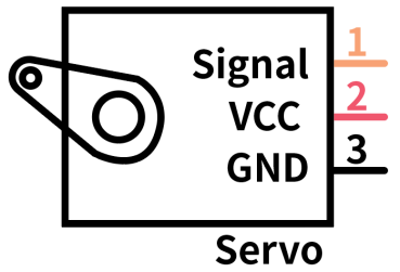
In general, servo has three lines in brown, red and orange. The brown wire is grounded, the red one is a positive pole line and the orange one is a signal line.
The rotation angle of servo motor is controlled by regulating the duty cycle of PWM (Pulse-Width Modulation) signal. The standard cycle of PWM signal is 20ms (50Hz). Theoretically, the width is distributed between 1ms-2ms, but in fact, it’s between 0.5ms-2.5ms. The width corresponds the rotation angle from 0° to 180°. But note that for different brand motors, the same signal may have different rotation angles.
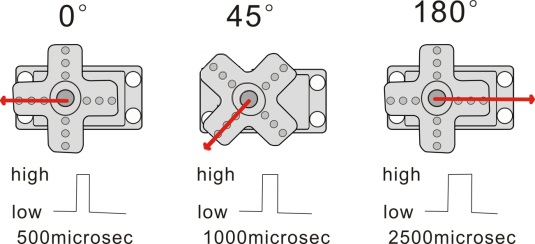
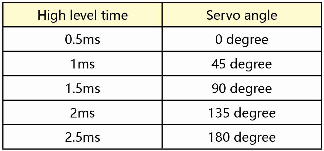
The corresponding servo angles are shown below:
2.Specification
Working voltage: DC 4.8V ~ 6V
Operating angle range: about 180 ° (at 500 → 2500 μsec)
Pulse width range: 500 → 2500 μsec
No-load speed: 0.12 ± 0.01 sec / 60 (DC 4.8V) 0.1 ± 0.01 sec / 60(DC 6V)
No-load current: 200 ± 20mA (DC 4.8V) 220 ± 20mA (DC 6V)
Stopping torque: 1.3 ± 0.01kg · cm (DC 4.8V) 1.5 ± 0.1kg · cm (DC6V)
Stop current: ≦ 850mA (DC 4.8V) ≦ 1000mA (DC 6V)
Standby current: 3 ± 1mA (DC 4.8V) 4 ± 1mA (DC 6V)
3.Components
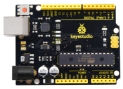
Development Board *1 |
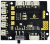
8833 Motor Driver *1 |
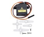
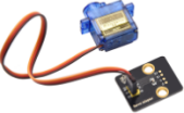
Servo*1 |
|---|---|---|
|
|
|
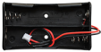
18650 Battery Holder*1 |
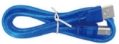
USB Cable*1 |
18650 Battery*2(self-provided) |
|
|
|

4.Wiring Diagram
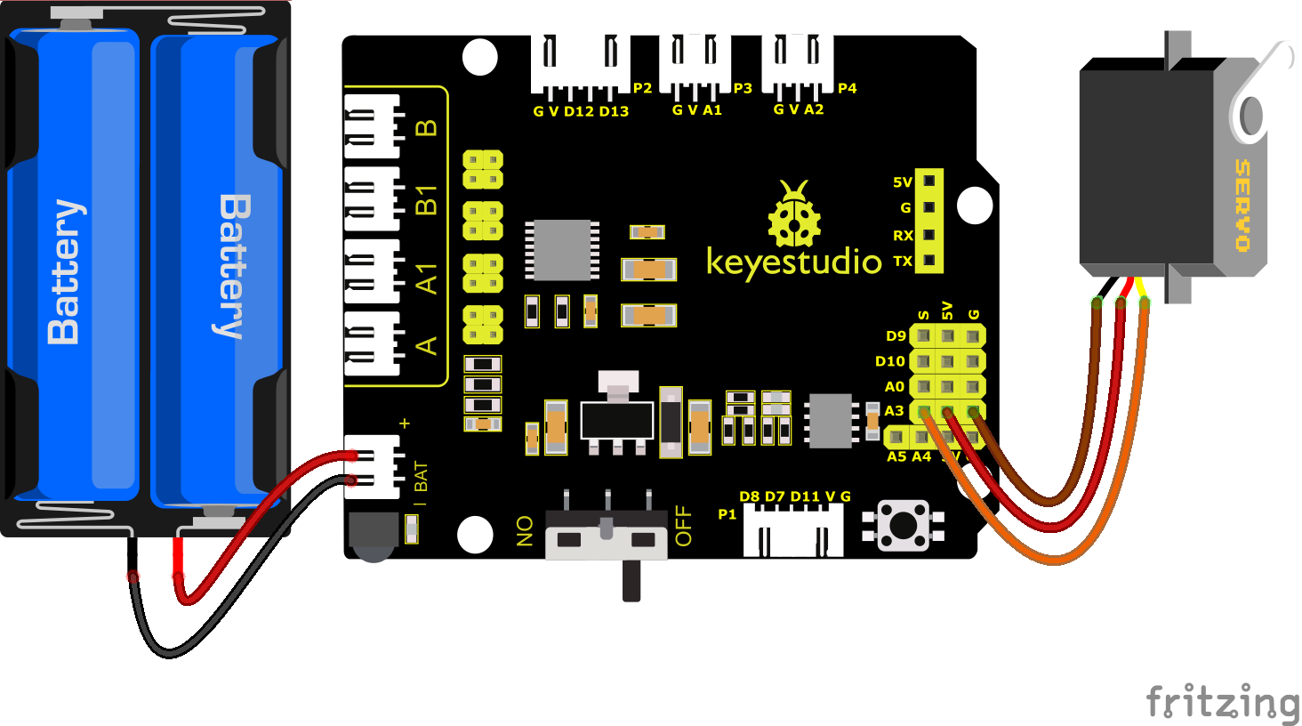
Wiring note: The servo is connected to G(GND)、V(VCC)and A3, the brown line of servo is linked with Gnd(G), the red one is connected to 5v(V) and the orange one is attached to A3.
The servo is obliged to connect to the external power due to its high demand for driving servo current. Generally, the current of development board is not big enough. If without connecting the external power, the development board could be burnt.
5.Test Code
Before writing the code, it is necessary to import the servo library file. The specific steps are as follows:
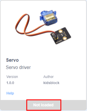
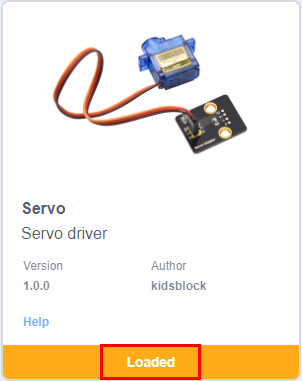
Click  to enter the extension library interface of sensors/modules/components, then look for “Servo”.
 component and click it. In this way, “Not Loaded” changes to “loaded”, indicating that “Servo” component was added successfully.
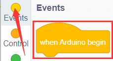
Click  to go back to the code editor, and in the modules area you can see the “Servo” component directive block added.
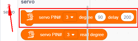
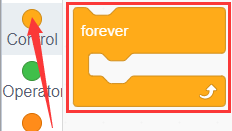
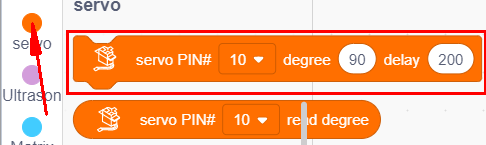
You can drag blocks to edit. Blocks listed below are for your reference.
(1).
(2).
(3).
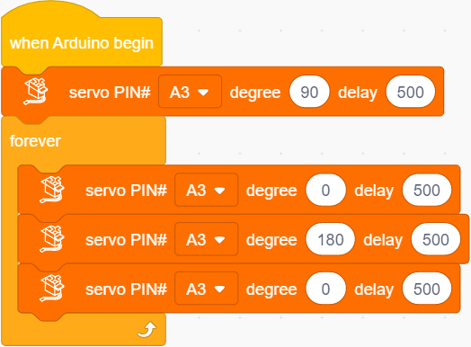
Complete Test Code
6.Test Result
After successfully uploading the code to the V4.0 board, connect the wirings according to the wiring diagram, and power on the external power. After powering on, turn the dip switch to the “ON” end, then servo will swing in the range of 0° to 180°.