Project 3: Line Tracking Sensor
1.Description
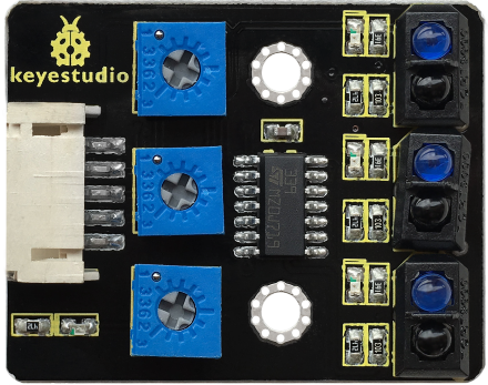
The tracking sensor is actually an infrared sensor. The component used here is the TCRT5000 infrared tube. Its working principle is to use different reflectivity of infrared light to colors, then convert the strength of the reflected signal into a current signal.
During the process of detection, black is active at HIGH level while white is active at LOW level. The detection height is 0-3 cm.
Keyestudio 3-channel line tracking module has integrated 3 sets of TCRT5000 infrared tubes on a board, which is more convenient for wiring and control.
By rotating the adjustable potentiometer on the sensor, it can adjust the detection sensitivity of the sensor.
2.Specification
Operating Voltage: 3.3-5V (DC)
Interface: 5PIN
Output Signal: Digital signal
Detection Height: 0-3 cm

Note: Before testing, rotate the potentiometer on the sensor to adjust the detection sensitivity. The sensitivity is best when adjusting the LED to a threshold between ON and OFF.
3.Components
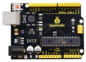
Development Board *1 |
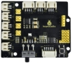
8833 Motor Driver *1 |
Red LED Module*1 |
Line Tracking Sensor*1 |
|---|---|---|---|
|
|
|
|
5P Dupont Wire*1 |
USB Cable*1 |
3P Dupont Wire*1 |
|
|
|
|


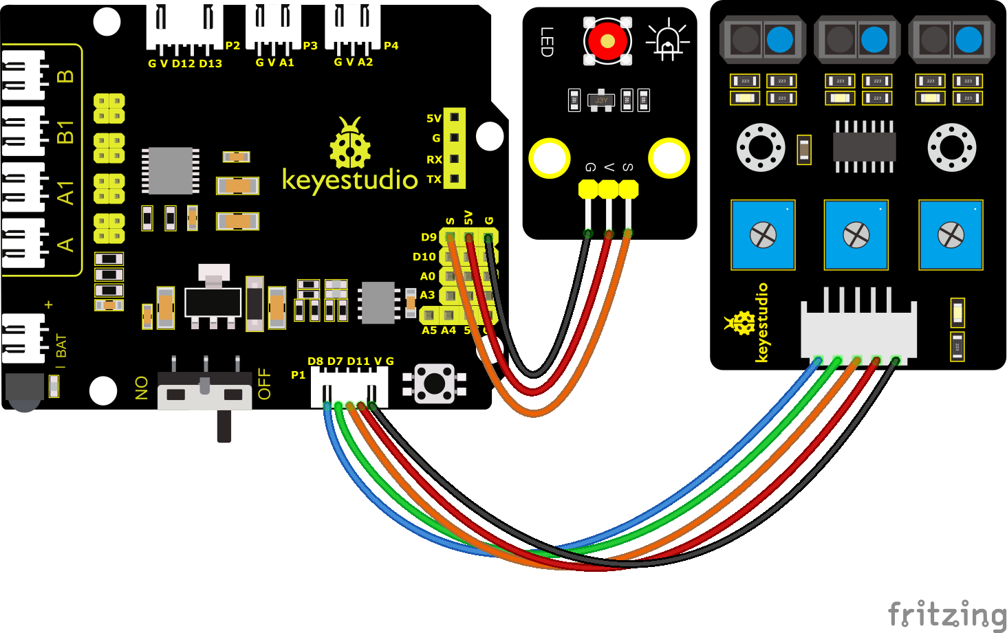
4.Wiring Diagram

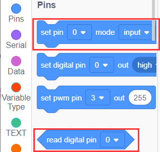
G, V, S1, S2 and S3 of the line tracking sensor are connected to G(GND), V(VCC), D11, D7 and D8 of the sensor expansion board.
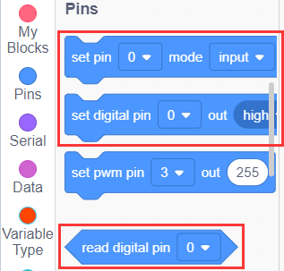
5.Test Code
You can drag blocks to edit. Blocks listed below are for your reference.
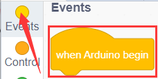
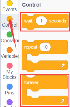
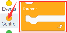
(1).
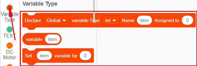
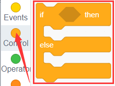
(2).
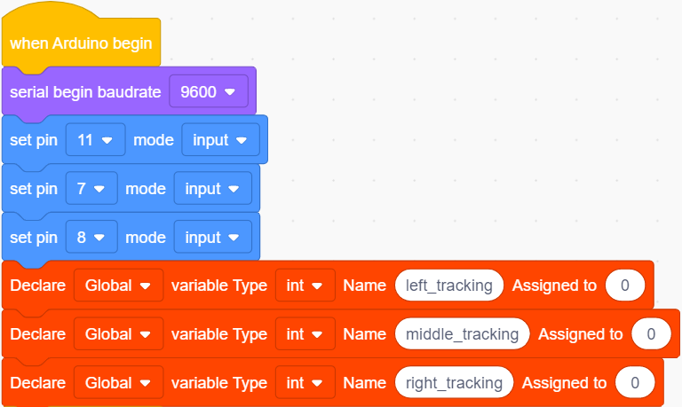
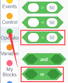
(3).
(4).
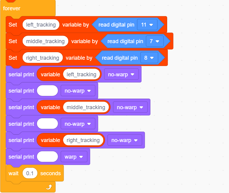
(5).
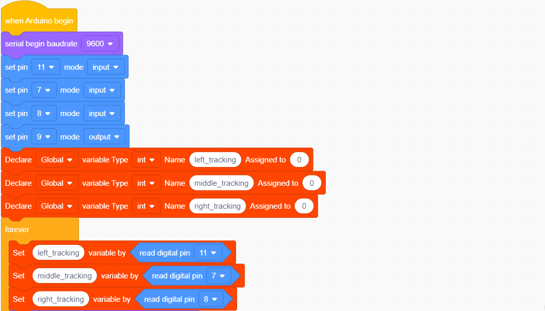
Complete Test Code
6.Test Result
After successfully uploading the code to the V4.0 board, connect the wirings according to the wiring diagram, and use a USB cable to connect the computer to power the board.
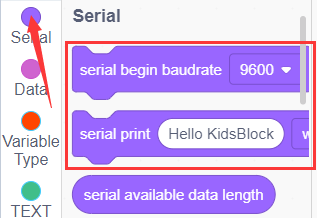
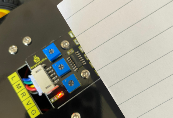
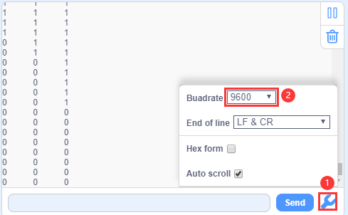
After powering on, click to set the baud rate to 9600 and you will view status of three line tracking sensors. When no signals are received, the value is 1. If we cover the sensor with a white paper, the value will be 0.
7.Extension Practice
After knowing its working principle, you can connect an LED to D9 so as to control LED by it.
You can drag blocks to edit. Blocks listed below are for your reference.
(1).
(2).
(3).
(4).
(5).
(6).
(7).
Complete Test Code
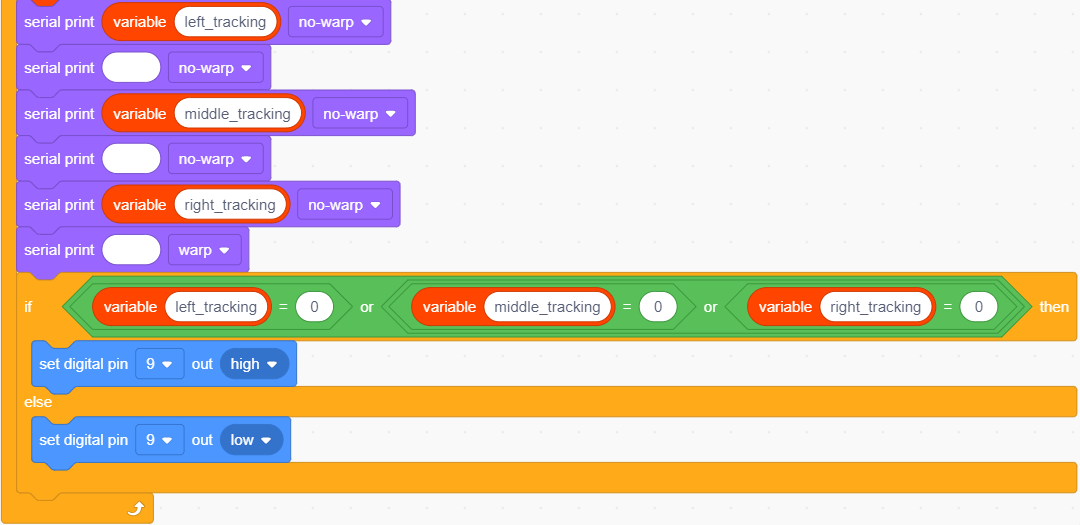
After successfully uploading the code to the V4.0 board, connect the wirings according to the wiring diagram, and use a USB cable to connect the computer to power the board.
After powering on, make a paper close to the sensor, then we can find the LED light up when covering the line tracking sensor.