Project 12 Ultrasonic Following Smart Car
1.Description
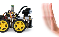
In this project, we will look to detect the distance between the 4WD smart car and the obstacles ahead through an ultrasonic sensor to drive two motors in a way that make the car move and make the 8*8 LED board show a smile facial pattern.
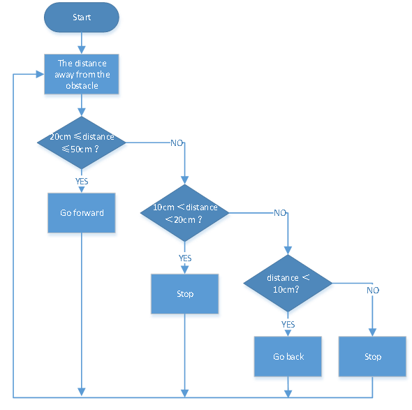
2.Flow Chart
| Detection | Measured distance of front obstacles | distance(unit:cm) |
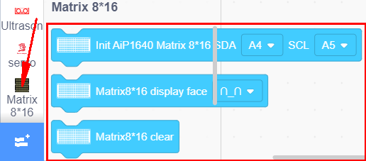
| Setting | 8*16 LED board shows a smile pattern. | |
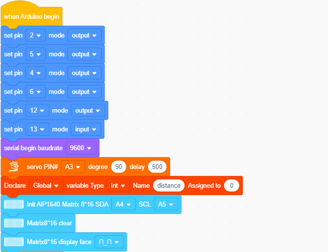
| Set servo to 90° | ||
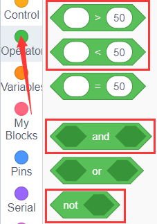
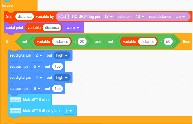
| Condition | distance≥20 and distance≤50 | |
| Status | Go forward | |
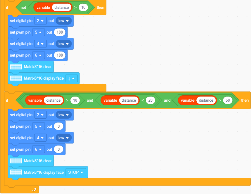
| Condition | distance>10 and distance<20 | |
| distance>50 | ||
| Condition | stop | |
| Condition | distance≤10 | |
| Condition | Go back |
3.Wiring Diagram
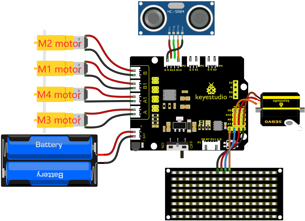
Wiring up:
1). GND, VCC, SDA and SCL of the 8*8 LED board are connected to G(GND), V(VCC), A4 and A5 of the expansion board.
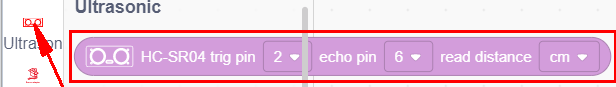
2). VCC, Trig, Echo and Gnd of the ultrasonic sensor are connected to 5V(V), D12(S), D13(S) and Gnd(G)
3). The servo is connected to G, V and A3. The brown wire is interfaced with Gnd(G), the red wire is interfaced with 5V(V) and the orange wire is interfaced with A3.
4). The power is connected to the BAT port
4.Test Code
Before writing the code, it is necessary to import the library files of the ultrasonic sensor, 8x16 LED board and the servo. The specific steps are as follows:
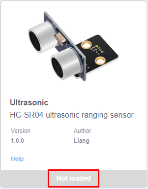
Click  to enter the extension library interface of sensors/modules/components, then search for“Ultrasonic”sensor
 and click it.
In this way, “Not loaded” changes to “loaded”, indicating that the“Ultrasonic”sensor was added successfully.

The 8x16 LED board and servo library files are added in the same way as the ultrasonic sensor.
Click  to return to the code editor interface, the instruction block of the added “Ultrasonic”sensor,“Matrix 8*16 Aip1640”module and “Servo”component can be seen in the module area.
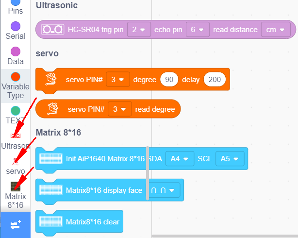
You can drag blocks to edit. Blocks listed below are for your reference
(1).
(2).
(3).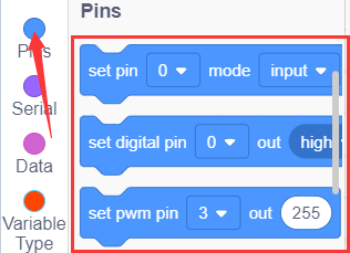
(4).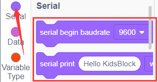
(5).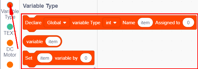
(6).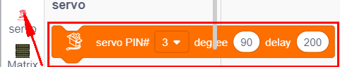
(7).
(8).
(9).
Complete Test Code
5.Test Result
After successfully uploading the code to the V4.0 board, connect the wirings according to the wiring diagram, power on the external power then turn the DIP switch to ON. Set the servo to 90°,the smart car will move with the obstacles and the 8X16 LED board will show“smile”.