Project 7 Bluetooth Remote Control
1.Description
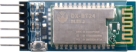
There is a DX-BT24 5.1 Bluetooth module in this kit. This bluetooth module comes with 256Kb space and complies with V5.1BLE bluetooth specification, which supports AT commands. Users can change parameters such as the baud rate and device name of the serial port as required.
Furthermore, it supports UART interface and bluetooth serial port transparent transmission, which also contains the advantages of low cost, small size, low power consumption and high sensitivity for sending and receiving. Notably, it solely needs a few peripheral components to realize its powerful functions.
2.Specification
Bluetooth protocol: Bluetooth Specification V5.1 BLE
Working distance: In an open environment, it can achieve 40m ultra-long distance communication
Operating frequency: 2.4GHz ISM band
Communication interface: UART
Bluetooth certification: Accord with FCC CE ROHS REACH certification standard
Serial port parameters: 9600, 8 data bits, 1 stop bit, invalid bit, no flow control
Power: 5V DC
Operating temperature: –10℃ to +65℃
3.Application
The DX-BT24 module also supports the BT5.1 BLE protocol, which can be directly connected to iOS devices with BLE Bluetooth function, and supports resident running of background programs. It is mainly used in the field of short-distance data wireless transmission. It enables to avoid cumbersome cable connections and can directly replace serial cables.
Successful application areas of BT24 modules:
※ Bluetooth wireless data transmission;
※ Mobile phone, computer peripheral equipment;
※ Handheld POS equipment;
※ Wireless data transmission of medical equipment;
※ Smart home control;
※ Bluetooth printer;
※ Bluetooth remote control toys;
※ Shared bicycles;
Ports
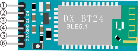
①STATE:Status pin
②RX:Receiving pin
③TX:sending pin
④GND:GND
⑤VCC:Power
⑥EN: Enable pin
Connect the BT module to the development board.
| Uno | BT24 |
| TX | RX |
| RX | TX |
| VCC | 5V |
| GND | GND |
4.Components
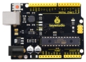
Development Board *1 |
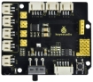
8833 Motor Driver *1 |
Red LED Module*1 |
|---|---|---|
|
|
|
3P F-F Dupont Wire*1 |
USB Cable*1 |
DX-BT24 Bluetooth Module*1 |
|
|
|


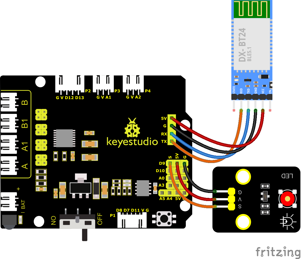
5.Wiring Diagram
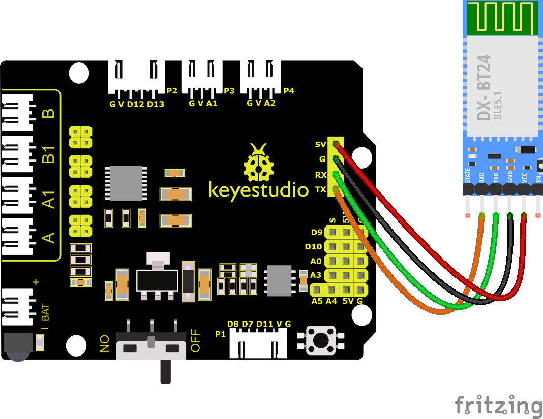
RXD, TXD, GND and VCC of the BT module are connected to TX, RX, G and 5V.
STATE and BRK of the BT module don’t need connection.
Note: the direction of the BT module when inserting it onto the 8833 board. And don’t insert it before uploading the code.
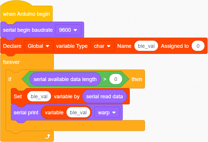
6.Test Code
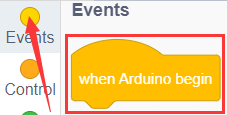
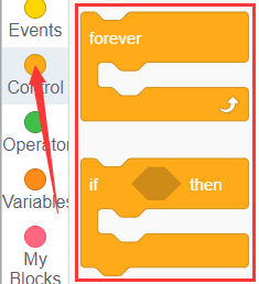
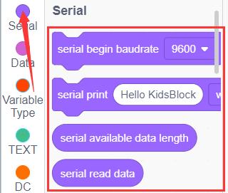
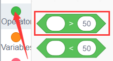
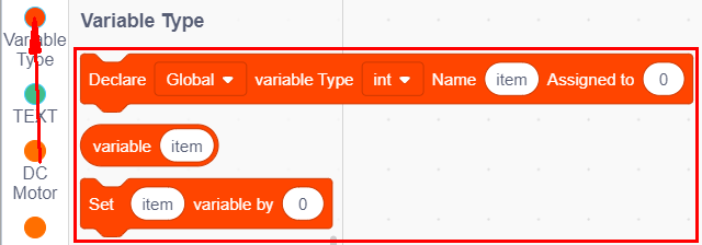
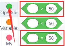
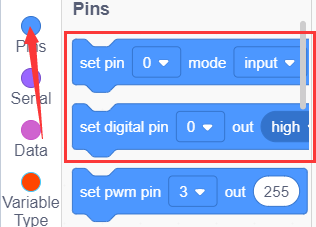
You can drag blocks to edit. Blocks listed below are for your reference.
(1).
(2).
(3).
(4).
(5).
Complete Test Code
Note: Before uploading the test code, you need to remove the Bluetooth module, otherwise the code will fail to be uploaded.Connect the Bluetooth module after uploading the code successfully.
7.Test Result
After successfully uploading the code to the V4.0 board, connect the wirings according to the wiring diagram, then connect the computer via a USB cable to power the board. After powering on, insert the BT module and the LED will flash, then we need to download the BT app.
8.Download Bluetooth APP
Apple system
(1).Open the App Store on the iPhone.
(2).Search keyes BT car and download the APP to your phone.
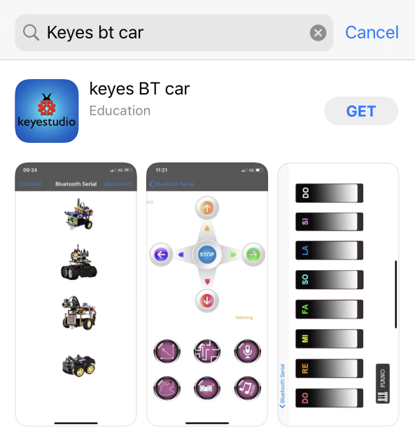
(3).After installation, enter its interface.
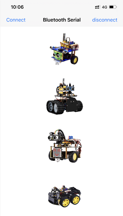
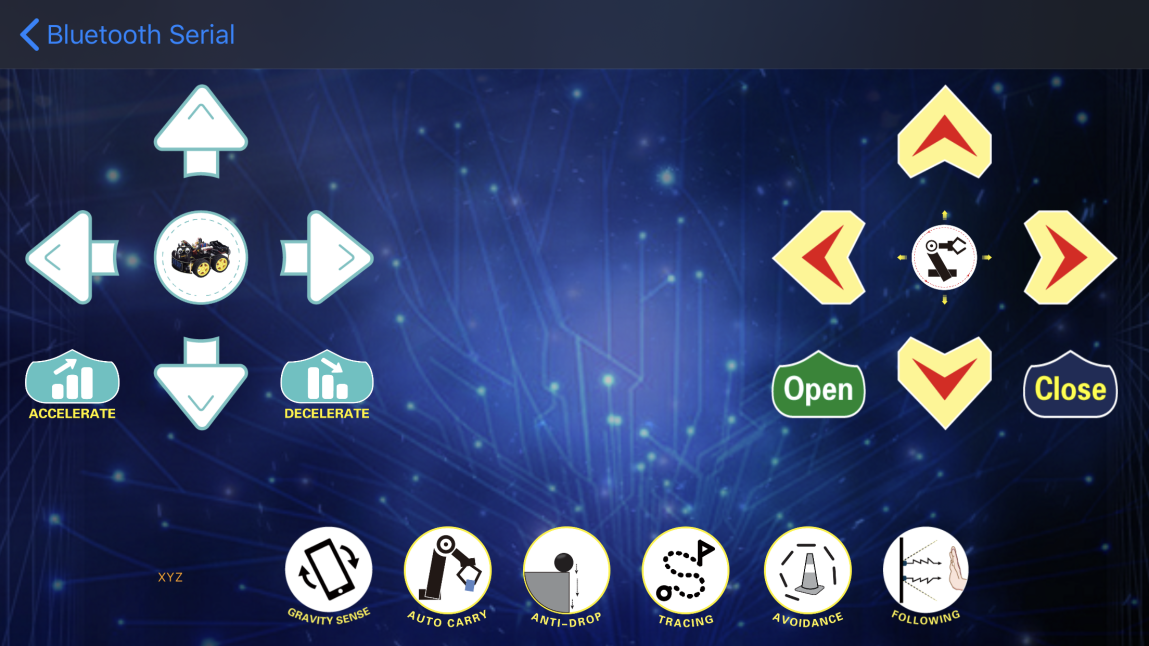
(4).Click “Connect” button in the upper left corner to automatically search for Bluetooth. When BT24 is found, click “Connect” to connect Bluetooth, and then click  to enter the control interface of 4WD smart car.
Android System
(1).Enter google play store to search for“keyes 4wd”.
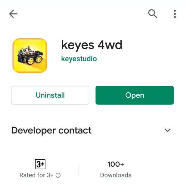
(2).The app icon is shown below after installation.

(3).Click app to enter the following page.
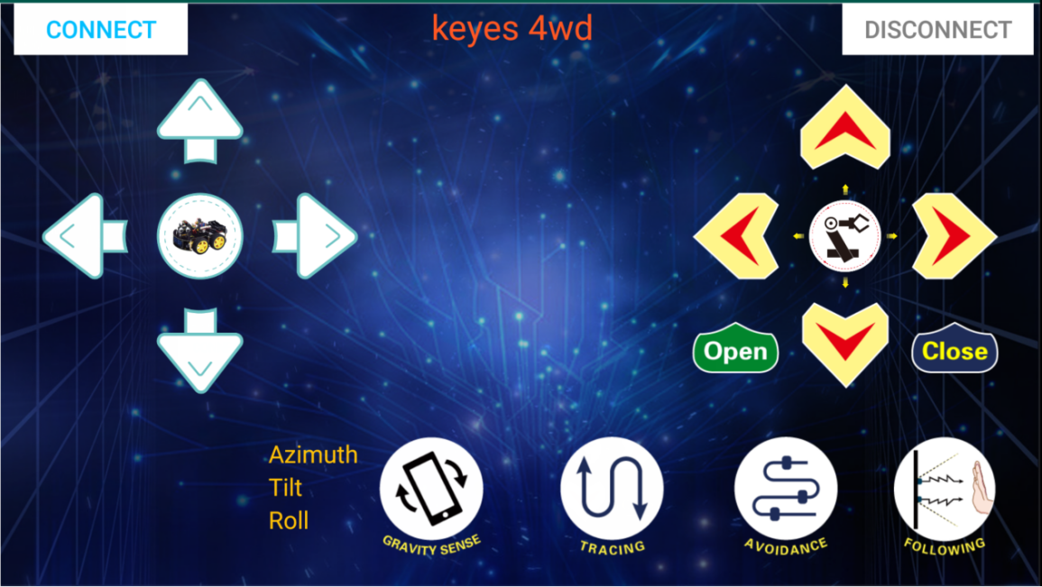
(4).After connecting Bluetooth, plug in power and LED indicator of Bluetooth module will flicker. Tap“Connect”to search the Bluetooth.

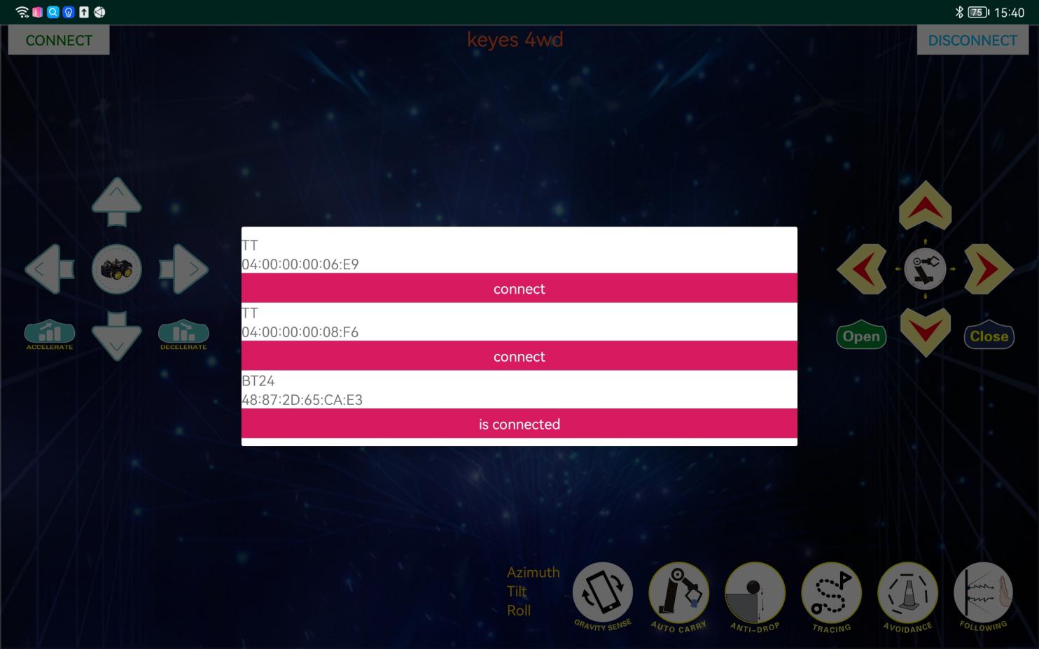
(5).When BT24 is found, click “connect” to connect Bluetooth. When “connect” turns into “is connected”, it indicates that the Bluetooth connection is successful. As shown in the picture below, the Bluetooth LED becomes will stay on.
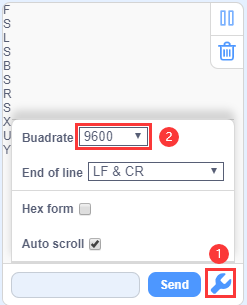
(6).After connecting Bluetooth module, click  to set baud rate to 9600. Pressing the button of the Bluetooth APP, and the corresponding characters will be displayed, as shown below:
Key |
Function |
|---|---|
|
Pair DX-BT24 5.1 Bluetooth module |
|
Disconnect Bluetooth |


Control character |
Function |
|
|---|---|---|
|
Press: F |
Press the button, the car goes front; |
|
Press: L |
Press the button, the car turns left; |
|
Press: R |
Press the button, the car turns right; |
|
Press: B |
Press the button, the car goes back; |
|
Press: “a” |
Click to speed up(maximum:255) |
|
Press: “d” |
Click to slow down(minimum:0) |
|
Click to start the gravity |
|
|
Click to send“X”, |
Start line tracking function; |
|
Click to send“Y”, |
Start ultrasonic avoiding function; |
|
Click to send“U”, |
Start ultrasonic follow function; |
|
Click to send“G”, |
Start restricting function; |


9.Extension Practice
Here we look to use the command sent by the mobile phone to turn on or off an LED light. Looking at the wiring diagram, an LED is connected to the D9 pin.
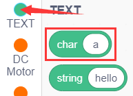
You can drag blocks to edit. Blocks listed below are for your reference.
(1).
(2).
(3).
(4).
(5).
(6).
(7).
Complete Test Code
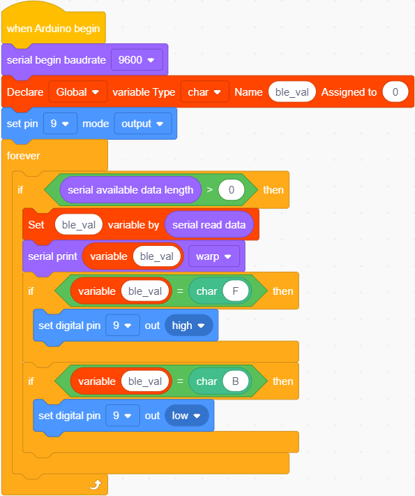
After successfully uploading the code to the V4.0 board, connect the wirings according to the wiring diagram, then connect the computer via a USB cable to power the board. After powering on, click