Project 6 IR Reception
1.Description
There is no doubt that infrared remote control is ubiquitous in daily life. It is used to control various household appliances, such as TVs, stereos, video recorders and satellite signal receivers. Infrared remote control is composed of infrared transmitting and infrared receiving systems, that is, an infrared remote control and infrared receiving module and a single-chip microcomputer capable of decoding.

The 38K infrared carrier signal emitted by remote controller is encoded by the encoding chip in the remote controller. It is composed of a section of pilot code, user code, user inverse code, data code, and data inverse code. The time interval of the pulse is used to distinguish whether it is 0 or 1 signal and the encoding is made up of these 0, 1 signals.
The user code of the same remote control is constant while the data code can distinguish the key.
When the remote control button is pressed, the remote control sends out an infrared carrier signal. When the IR receiver receives the signal, the program will decode the carrier signal and determines which key is pressed. The MCU decodes the received 01 signal, thereby judging what key is pressed by the remote control.
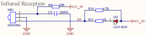
Infrared receiver we use is an infrared receiver module. Mainly composed of an infrared receiver head, which is a device that integrates reception, amplification, and demodulation. Its internal IC has completed demodulation, and can achieve from infrared reception to output and be compatible with TTL signals.
Additionally, it is suitable for infrared remote control and infrared data transmission. The infrared receiving module made by the receiver has only three pins, signal line, VCC and GND. It is very convenient to communicate with Arduino and other microcontrollers.
2.Specification
Operating Voltage: 3.3-5V(DC)
Output Signal: Digital signal
Receiving Angle: 90 degrees
Frequency: 38khz
Receiving Distance: 10m
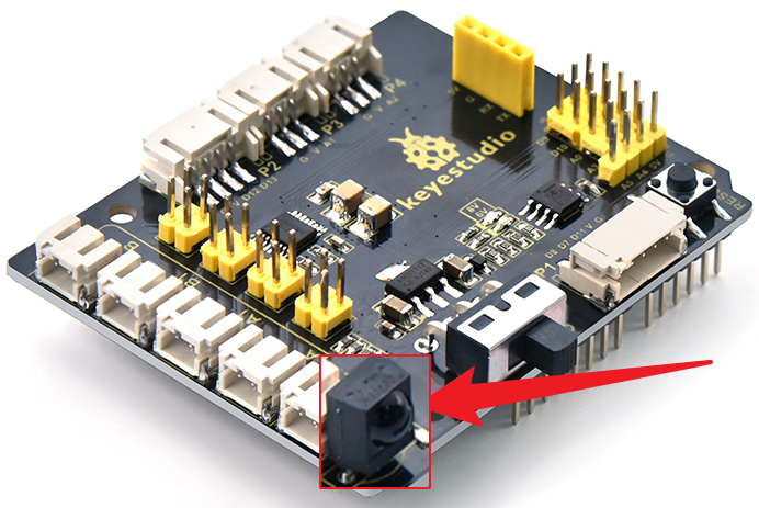
The picture shows the real product and circuit diagram of the infrared receiver.
3.Components
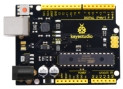
Development Board *1 |
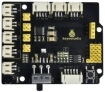
8833 Motor Driver *1 |
Red LED Module*1 |
|---|---|---|
|
|
|
3P F-F Dupont Wire*1 |
USB Cable*1 |
|
|
|


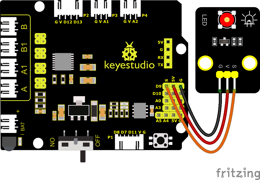
Since the 8833 board integrates with the IR receiver, it doesn’t need wiring up. Pins of IR receiver module are G(GND), V(VCC)and D3.
4.Test Code
Please note: The infrared module shown in the software demonstration is already integrated into the expansion board and is not supplied separately. Consequently, you will not find the module depicted in the image below within the product.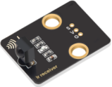
Before writing the code, it is necessary to import the library file of the IR receiver sensor. The specific steps are as follows:
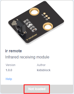
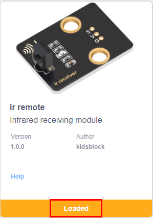
Click  to enter the extension library interface of sensors/modules/components, then search for“ir remote” sensor and click it. In this way, “Not loaded” changes to “loaded”, indicating that ir remote”sensor was added successfully.
Click  to return to the code editor interface, the instruction block of the added “ir remote”sensor can be seen in the module area.
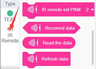
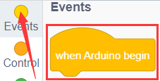
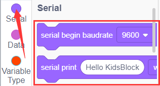
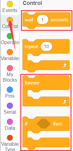
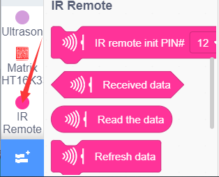
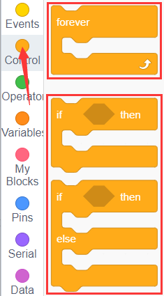
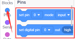
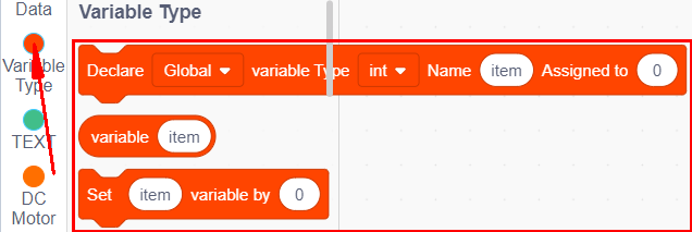
You can drag blocks to edit. Blocks listed below are for your reference.
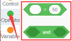
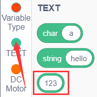
(1).
(2).
(3).
(4).
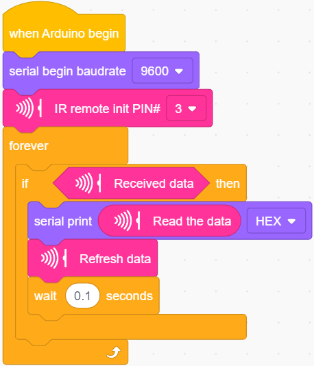
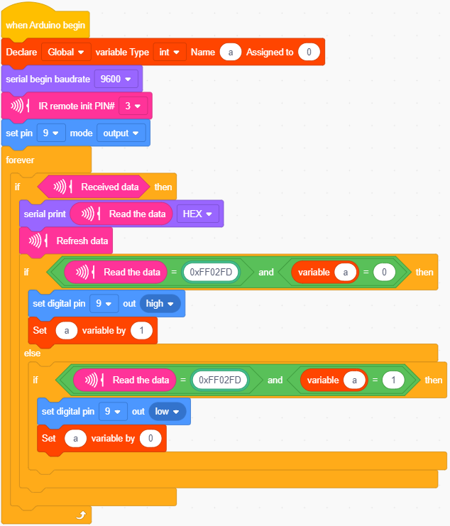
Complete Test Code
5.Test Result
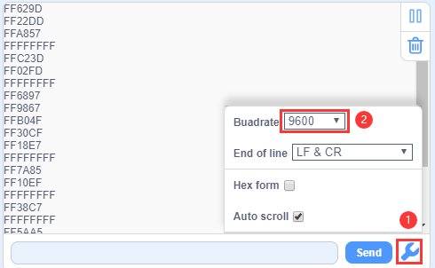
After successfully uploading the code to the V4.0 board, connect the wirings according to the wiring diagram, then connect the computer via a USB cable to power the board. After powering on, click  to set baud rate to 9600.
Take out the remote control, and send signal to the infrared receiver sensor. You can see the key value of the corresponding key, if the key time is too long, FFFFFFFF is prone to garbled characters.
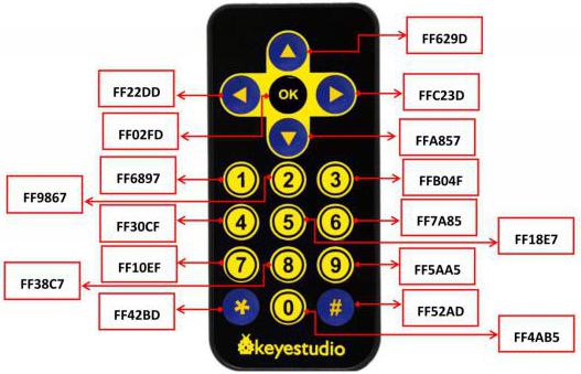
The keys value of remote control are shown below.
6.Extension Practice
We have decoded the key value of the IR remote control. How about controlling LED by the measured value? We could design an experiment.
Attach an LED to D9, then press the keys of remote control to make LED light on and off.
You can drag blocks to edit. Blocks listed below are for your reference.
(1).
(2).
(3).
(4).
(5).
(6).
(7).
(8).
Complete Test Code
After successfully uploading the code to the V4.0 board, connect the wirings according to the wiring diagram, then connect the computer via a USB cable to power the board. After powering on, press the “OK” key on remote control can make the LED on and off.