Project 6:Geomagnetic Sensor
1. Description
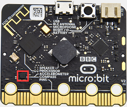
This project mainly introduces the use of the micro:bit’s geomagnetic sensor. In addition to detecting the strength of the magnetic field, it can also be used to determine the direction, which is an important part of the heading and attitude reference system (AHRS) as well.
It uses FreescaleMAG3110 three-axis magnetometer. Its I2C interface communicates with the outside, and the range is ±1000µT, the maximum data update rate is 80Hz. Combined with an accelerometer, it can calculate the position. Additionally, it is applied to magnetic detection and compass blocks.
Then we could read the value detected by it to determine the location. We need to calibrate the micro:bit board when the magnetic sensor works. The correct calibration method is to rotate the micro:bit board.
In addition, the objects nearby may affect the accuracy of readings and calibration.
2. Preparation
A. Attach the micro:bit main board to your computer via the USB cable
B. Open the offline version of Mu.
3. Test Code1
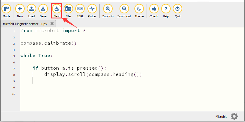
Enter Mu software and open the file“Magnetic sensor -1.py“ to import code. You can also input the code in the editing window yourself.
(Note: All words and symbols must be written in English.)
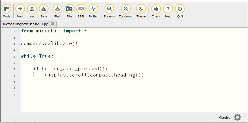
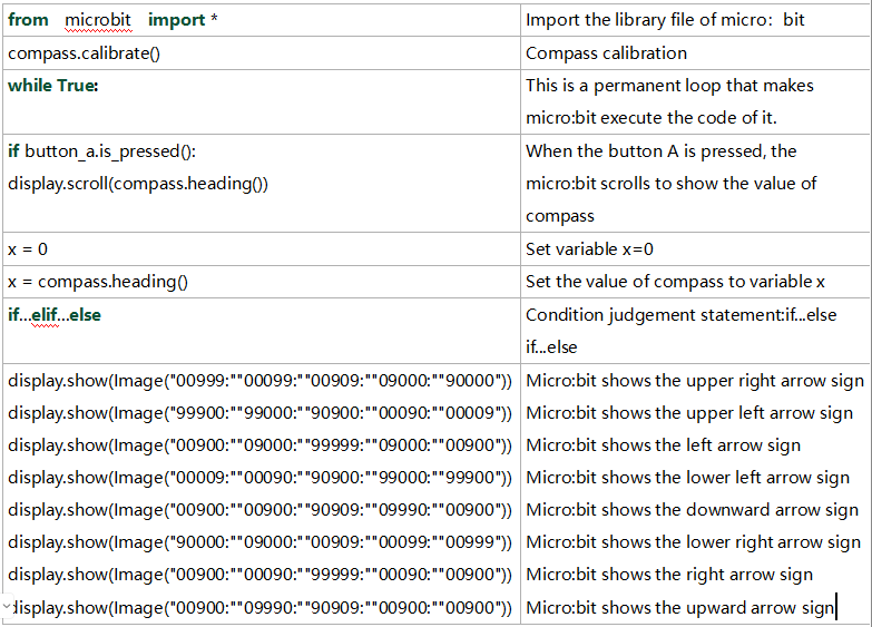
from microbit import *

compass.calibrate()

while True:

    if button_a.is_pressed():
        display.scroll(compass.heading())
Click“Check”to examine errors in the code. The program proves wrong if underlines and cursors are shown.
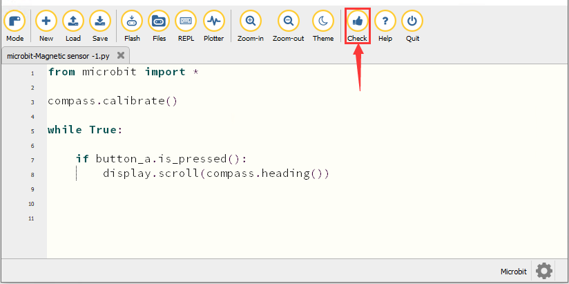
If the code is correct, connect micro:bit to the computer and click“Flash”to download the code to the micro:bit board.
4. Test Result1
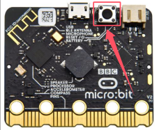
After downloading the code to the board successfully, power on via micro USB cable or external power supply(turn the DIP switch to ON), and press the reset button on micro:bit.
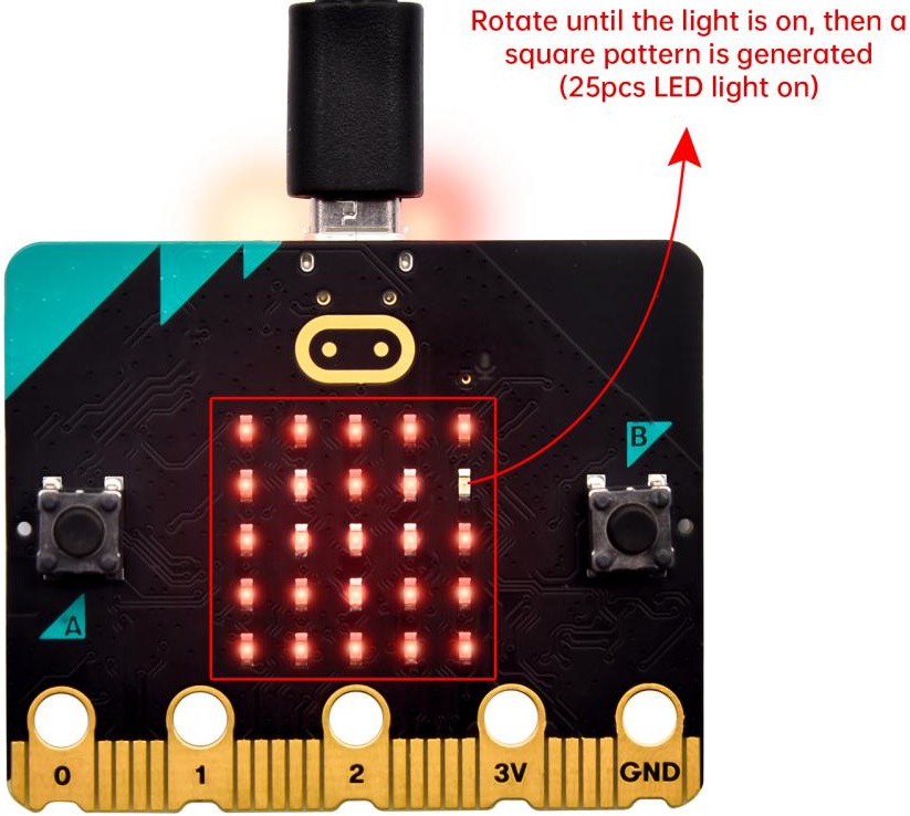
The LED dot matrix shows “TILT TO FILL SCREEN”. Pressing the button A, the board asks us to calibrate the compass. Then enter the calibration page. Rotate the board until all 25 red LEDs are on, as shown below.
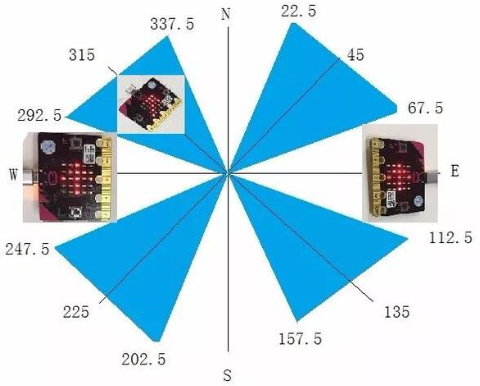
After that, a smile pattern  appears, which implies the calibration is done. When the calibration process is completed, pressing the button A will make the magnetometer reading display directly on the screen. And the direction north, east, south and west correspond to 0°, 90°, 180° and 270° respectively.
5. Test Code2
For the below picture, the arrow will work to point to the upper right when the value ranges from 292.5 to 337.5. Since 0.5 can’t be input in the code, the values we get are 293 and 338.
Then add other statements to make a set of complete code.
Enter Mu software and open the file“Magnetic sensor -2.py“ to import the code. You can also input code in the editing window yourself.
(Note: All words and symbols must be written in English.)
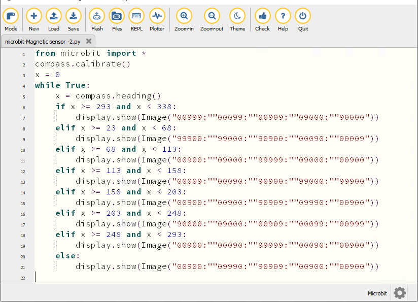
from microbit import *
compass.calibrate()
x = 0
while True:
    x = compass.heading()
    if x >= 293 and x < 338:
        display.show(Image("00999:""00099:""00909:""09000:""90000"))
    elif x >= 23 and x < 68:
        display.show(Image("99900:""99000:""90900:""00090:""00009"))
    elif x >= 68 and x < 113:
        display.show(Image("00900:""09000:""99999:""09000:""00900"))
    elif x >= 113 and x < 158:
        display.show(Image("00009:""00090:""90900:""99000:""99900"))
    elif x >= 158 and x < 203:
        display.show(Image("00900:""00900:""90909:""09990:""00900"))
    elif x >= 203 and x < 248:
        display.show(Image("90000:""09000:""00909:""00099:""00999"))
    elif x >= 248 and x < 293:
        display.show(Image("00900:""00090:""99999:""00090:""00900"))
    else:
        display.show(Image("00900:""09990:""90909:""00900:""00900"))
Click“Check”to examine errors in the code. The program proves wrong if underlines and cursors are shown.
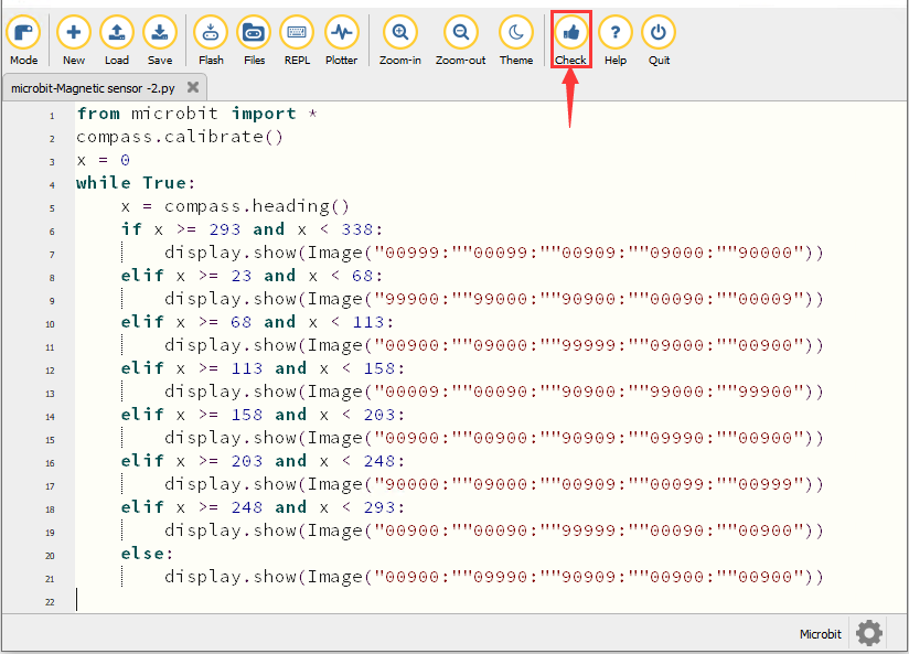
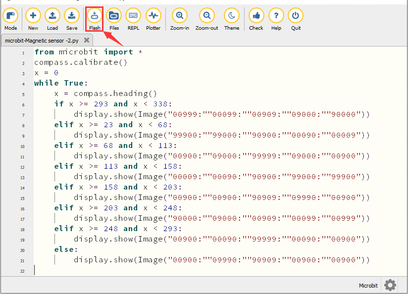
If the code is correct, connect the micro:bit to your computer and click“Flash”to download the code to the micro:bit board.
6. Test Result
After downloading the code to the board successfully, power on via micro USB cable or external power supply(turn the DIP switch to ON), and press the reset button on micro:bit.
After calibration, rotate the micro:bit board, then the LED dot matrix displays the direction signs.
7. Code Explanation