Project 17:Line Tracking Sensor
Project 17.1:Detect Line Tracking Sensor
1. Description
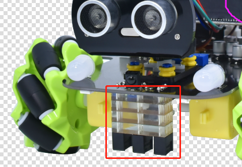
The motor driver board of the Keyestudio 4WD Mecanum Robot Car comes with a 3-channel line tracking sensor, which adopts TCRT5000 IR tubes and 3 potentiometers.
The TCRT5000 IR tube contains an IR emitting tube and an IR receiving tube. When the infrared signals of the emitting tube is received by the receiving tube through reflection, the resistance of the receiving tube will change, which is generally reflected in the voltage change on the circuit.
The resistance varies depending on the intensity of the infrared signals received by the receiving tube, which is often in the color of the reflecting surface and the distance of the reflecting surface receiving tube. At the time of detection, black is high level active and white is low level active.
2. Working Principle
When the car runs above a white road, the IR emitting tube installed under the car emits infrared signals to detect the road and the receiving tube will receive signals sending back. Then the output end outputs low level(0); when it detects black lines, it outputs high level(1).
The 3-channel tracking sensor integrated port on the 4WD Mecanum Robot Car is connected to the collection port of G ,5V ,P10, P4 and P3 on the micro:bit expansion board, which is controlled by the P10, P4 and P3 of the micro:bit. The left TCRT5000 infrared pair tube on the sensor is controlled by P3, the middle one is by P4 and the right one is by P10.
After putting a white paper on the bottom of the 4WD Mecanum Robot Car, we will rotate the potentiometers on the 3-way tracking sensor. When the indicator light on the sensor module is on, pick up the car to make the two wheels on the 4WD Mecanum Robot Car separate. The height of the white paper is about 1.5cm, when the indicator light on the sensor module is off, and then the sensitivity is adjusted.
**Note that since the 5*5 dot matrix uses the P3P4P6P7P10, we must turn off the dot matrix function when using the line tracking sensor. **
3. Preparation
Insert micro:bit board into the slot of keyestudio 4WD Mecanum Robot CarV2.0
Place batteries into battery holder
Dial power switch to ON end
Connect micro:bit to computer via an USB cable
Open the offline version of Mu.
4. Test Code
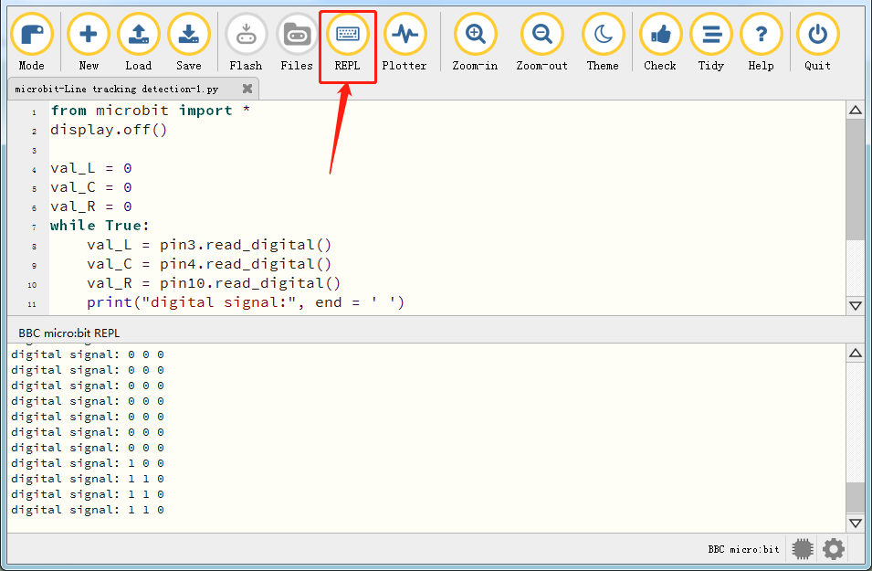
Enter Mu software and open the file“Line tracking detection.py”to import code. You can also input code in the edit window yourself.
(Note: All English words and symbols must be written in English.)
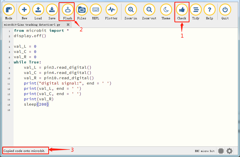
Click“Check”to examine errors in the code. The program proves wrong if underlines and cursors are shown.
If the code is correct, connect the micro:bit to your computer and click“Flash”to download the code to the micro:bit board.
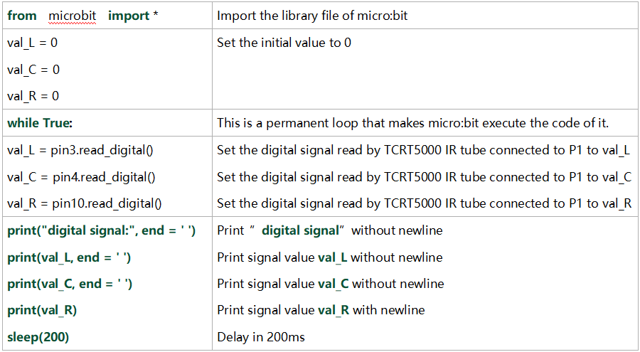
from microbit import *
display.off()

val_L = 0
val_C = 0
val_R = 0
while True:
    val_L = pin3.read_digital()
    val_C = pin4.read_digital()
    val_R = pin10.read_digital()
    print("digital signal:", end = ' ')
    print(val_L, end = ' ')
    print(val_C, end = ' ')
    print(val_R)
    sleep(200)
5. Test Result
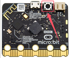
After downloading the code to the board successfully and don’t plug off the USB cable. Click“REPL”and then press the reset button.
The readings detected by the left TCRT5000 IR tube will be displayed on monitor.
When the left TCRT5000 IR tube detects the white object, 0 will be shown and the left indicator will be on; when there is only black object detected, 1 will be displayed and the indicator will be off, as shown below:
6. Code Explanation
Project 17.2:Tracking Smart Car
1. Description
In this lesson we will combine a line tracking sensor with a motor to make a line tracking smart car.
The micro:bit board will analyze the signals and control the smart car to show the line tracking function.
2. Working Principle
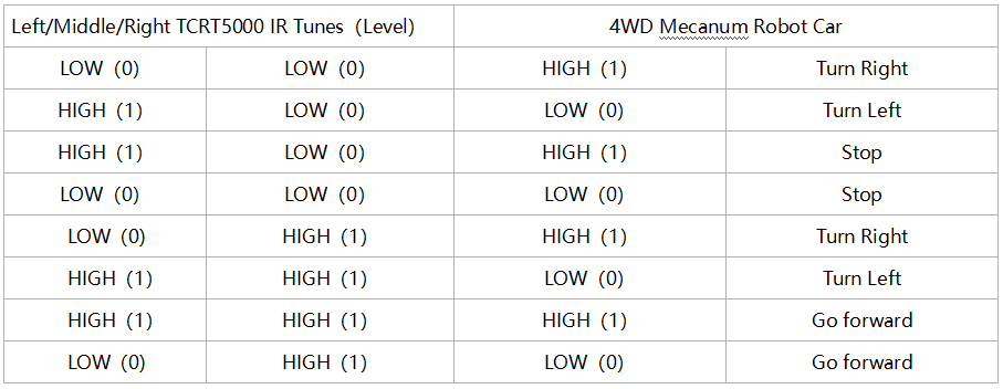
The smart car will make different moves according to the value received by the 3-channel line tracking sensor.
3. Preparation
Insert micro:bit board into the slot of keyestudio 4WD Mecanum Robot CarV2.0
Place batteries into battery holder
Dial power switch to ON end
Connect micro:bit to computer via an USB cable
Open the offline version of Mu.
Warning: The 3-way tracking sensor should be used in environment without infrared interference such as sunlight. Sunlight contains a lot 0f invisible light, such as infrared and ultraviolet. In an environmen with strong sunlight, the 3-way tracking sensor cannot work properly.
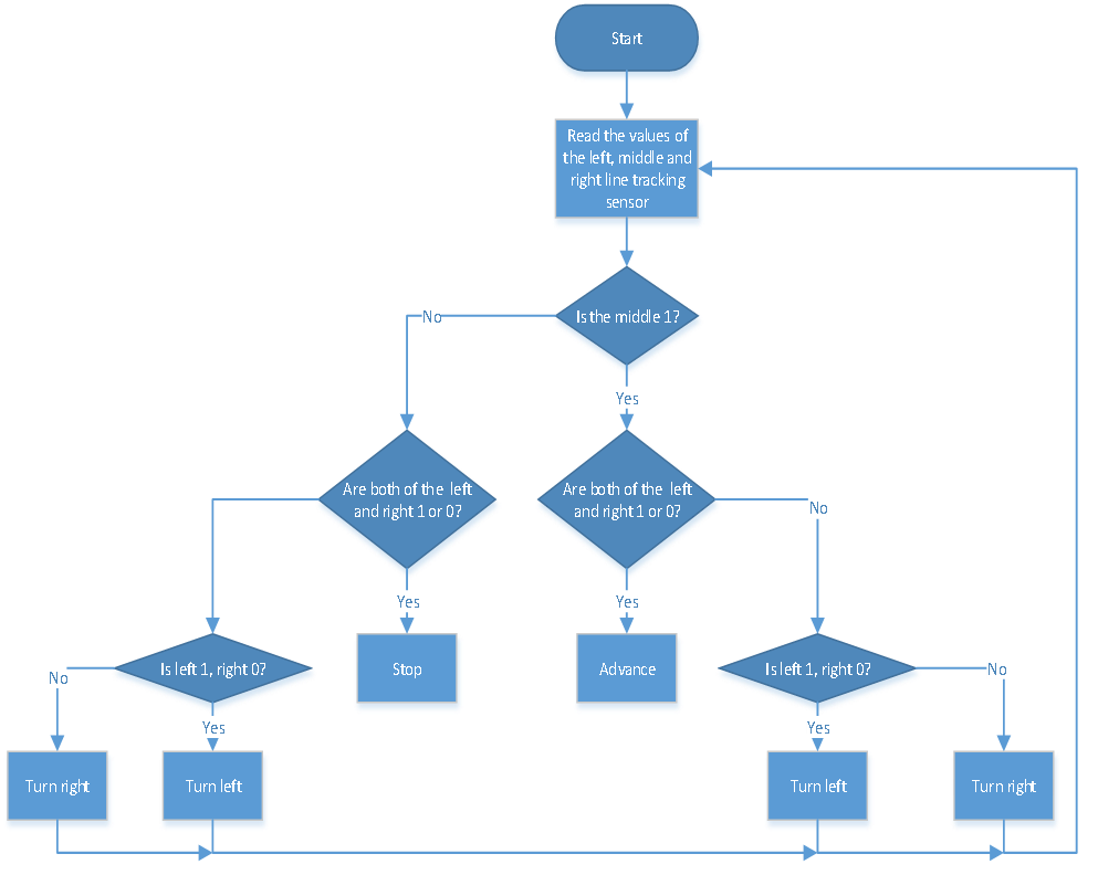
4. Flow Chart
5. Test Code
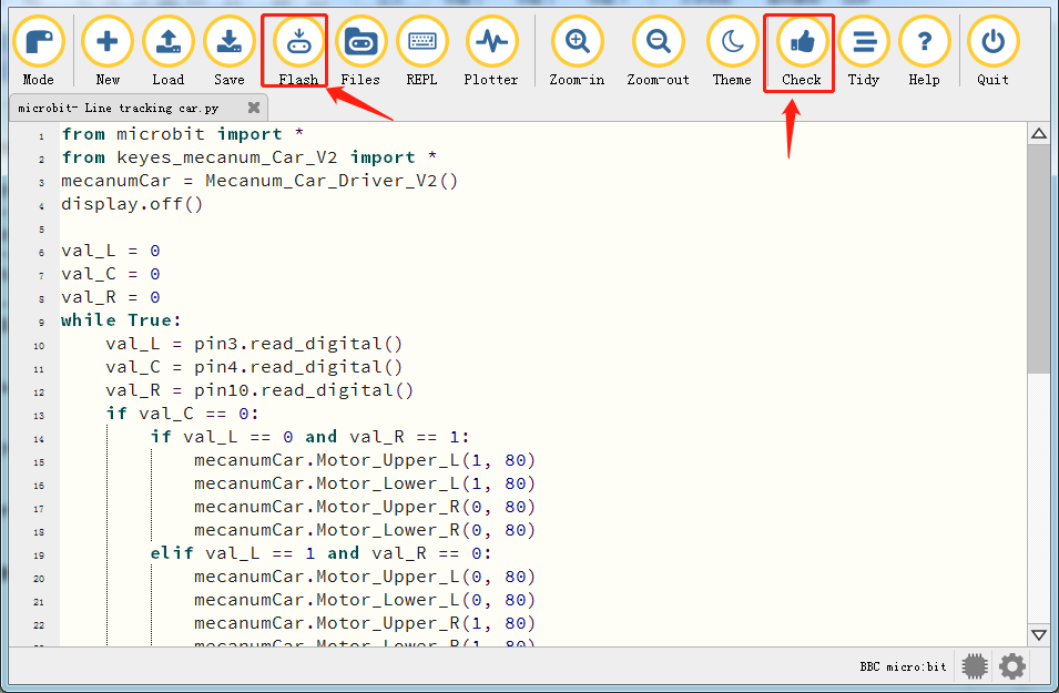
Enter Mu software and open the file“Line tracking car.py”to import code. You can also input code in the edit window yourself.
(Note: All English words and symbols must be written in English.)
Click“Files”to import“keyes_mecanum_Car.py”library file to micro:bit.
Click“Check”to examine errors in the code. The program proves wrong if underlines and cursors are shown.
If the code is correct, connect the micro:bit to your computer and click“Flash”to download the code to the micro:bit board.
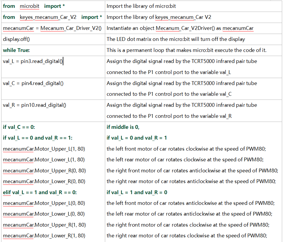
from microbit import *
from keyes_mecanum_Car_V2 import *
mecanumCar = Mecanum_Car_Driver_V2()
display.off()
val_L = 0
val_C = 0
val_R = 0
while True:
val_L = pin3.read_digital()
val_C = pin4.read_digital()
val_R = pin10.read_digital()
if val_C == 0:
if val_L == 0 and val_R == 1:
mecanumCar.Motor_Upper_L(1, 80)
mecanumCar.Motor_Lower_L(1, 80)
mecanumCar.Motor_Upper_R(0, 80)
mecanumCar.Motor_Lower_R(0, 80)
elif val_L == 1 and val_R == 0:
mecanumCar.Motor_Upper_L(0, 80)
mecanumCar.Motor_Lower_L(0, 80)
mecanumCar.Motor_Upper_R(1, 80)
mecanumCar.Motor_Lower_R(1, 80)
else:
mecanumCar.Motor_Upper_L(0, 0)
mecanumCar.Motor_Lower_L(0, 0)
mecanumCar.Motor_Upper_R(0, 0)
mecanumCar.Motor_Lower_R(0, 0)
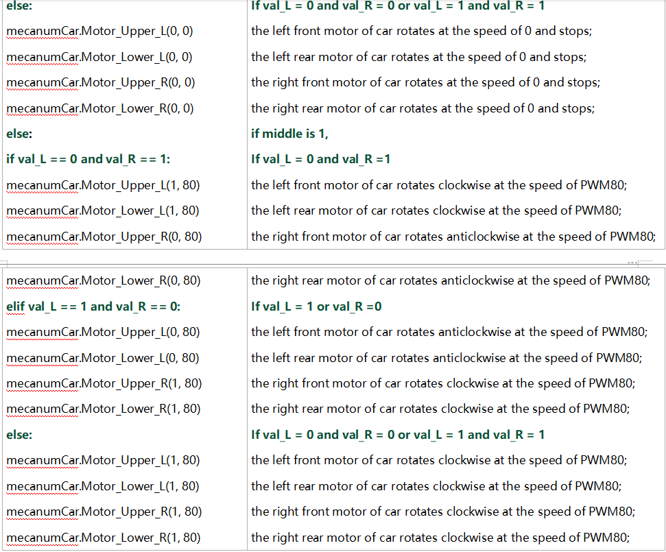
else :
if val_L == 0 and val_R == 1:
mecanumCar.Motor_Upper_L(1, 80)
mecanumCar.Motor_Lower_L(1, 80)
mecanumCar.Motor_Upper_R(0, 80)
mecanumCar.Motor_Lower_R(0, 80)
elif val_L == 1 and val_R == 0:
mecanumCar.Motor_Upper_L(0, 80)
mecanumCar.Motor_Lower_L(0, 80)
mecanumCar.Motor_Upper_R(1, 80)
mecanumCar.Motor_Lower_R(1, 80)
else:
mecanumCar.Motor_Upper_L(1, 80)
mecanumCar.Motor_Lower_L(1, 80)
mecanumCar.Motor_Upper_R(1, 80)
mecanumCar.Motor_Lower_R(1, 80)
6. Test Result
After downloading the code to the board successfully, external power supply(turn the DIP switch to ON),and press the reset button on micro:bit.
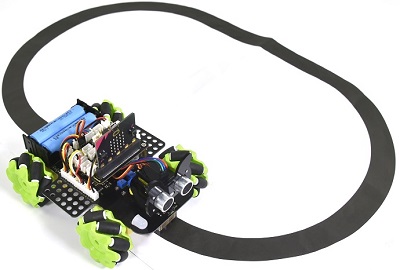
The line tacking car goes forward along the black line .
Note: (1)The width of black line should be equal to or larger than the width of the line tracking sensor when tracking.
(2)Avoid to test the smart car under the strong light.
7. Code Explanation