Project 7:Accelerometer
1. Description
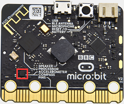
The micro: bit main board V2 has a built-in LSM303AGR gravity acceleration sensor, also known as accelerometer, with a resolution of 8/10/12 bits. The code section sets the range to 1g, 2g, 4g, and 8g.
We often use an accelerometer to detect the status of machines.
In this project, we will work to introduce how to measure the position of the board with the accelerometer. And then have a look at the original three-axis data output by the accelerometer.
2. Preparation
A. Attach the micro:bit main board to your computer via the USB cable
B. Open the offline version of Mu.
3. Test Code1
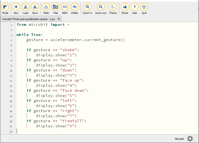
Enter Mu software and open the file“Three-axis acceleration sensor -1.py“ to import the code. You can also input the code in the editing window yourself.
(Note: All words and symbols must be written in English.)
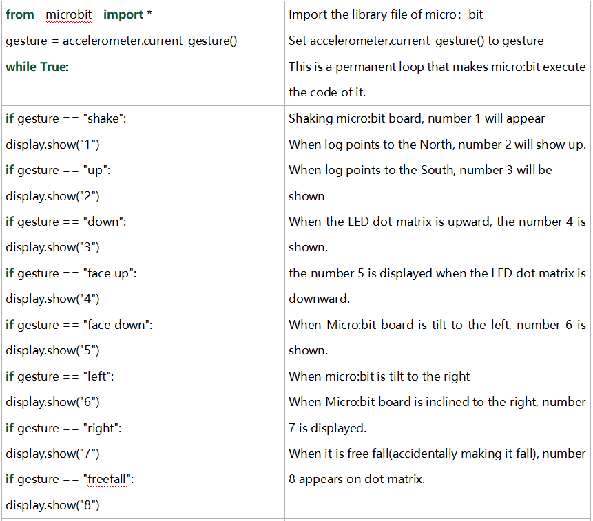
from microbit import *

while True:
    gesture = accelerometer.current_gesture()

    if gesture == "shake":
        display.show("1")
    if gesture == "up":
        display.show("2")
    if gesture == "down":
        display.show("3")
    if gesture == "face up":
        display.show("4")
    if gesture == "face down":
        display.show("5")
    if gesture == "left":
        display.show("6")
    if gesture == "right":
        display.show("7")
    if gesture == "freefall":
        display.show("8")
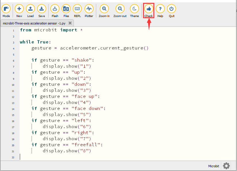
Click“Check”to examine errors in the code. The program proves wrong if underlines and cursors are shown.
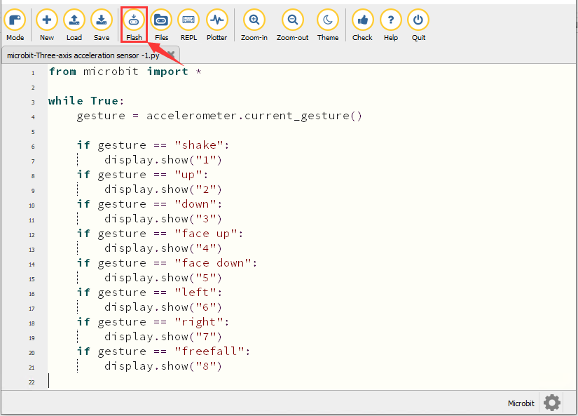
If the code is correct, connect the micro:bit to your computer and click“Flash”to download the code to the micro:bit board.
4. Test Result1
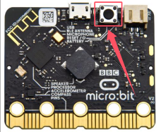
After downloading the code to the board successfully, power on via micro USB cable or external power supply(turn the DIP switch to ON), and press the reset button on micro:bit.
When we shake the micro: bit main board,no matter at any direction, the LED dot matrix displays the digit “1”.
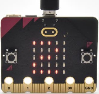
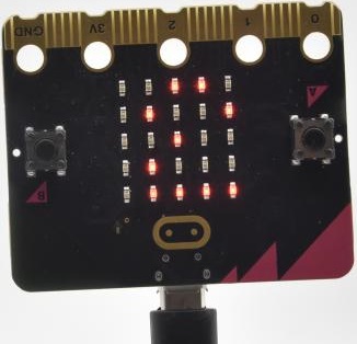
When it is kept upright(make its logo above the LED dot matrix), the number 2 appears.
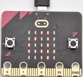
When it is kept upside down( make its logo below the LED dot matrix) , it shows as below.
When it is placed still on the desk, showing its front side, the number 4 appears.
When it is placed still on the desk, showing its back side, the number 5 exhibits.
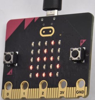
When the board is tilted to the left , the LED dot matrix shows the number 6, as shown below:
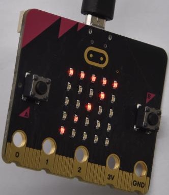
When the board is tilted to the right , the LED dot matrix displays the number 7, as shown below:
When the board is knocked to the floor, this process can be considered as a free fall and the LED dot matrix shows the number 8. (Please note that this test is not recommended for it may damage the main board.)
Attention: If you’d like to try this function, you can also set the acceleration to 3g, 6g or 8g.
5. Test Code2
Enter Mu software and open the file“Three-axis acceleration sensor -2.py“ to import the code. You can also input the code in the editing window yourself.
(Note: All words and symbols must be written in English.)
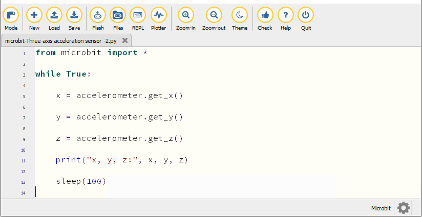
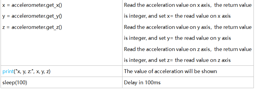
from microbit import *

while True:

    x = accelerometer.get_x()

    y = accelerometer.get_y()

    z = accelerometer.get_z()

    print("x, y, z:", x, y, z)

    sleep(100)
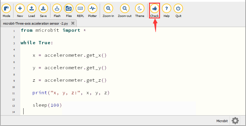
Click“Check”to examine errors in the code. The program proves wrong if underlines and cursors are shown.
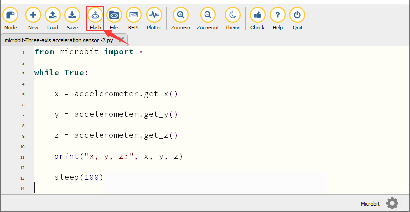
If the code is correct, connect the micro:bit to your computer and click“Flash”to download the code to the micro:bit board.
6. Test Result2
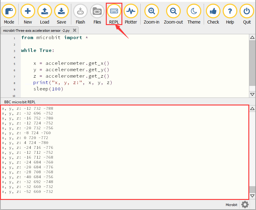
After downloading the code to the board successfully, power on via micro USB cable or external power supply(turn the DIP switch to ON). Click“REPL”and press the reset button on micro:bit.
Then REPL window will show the value of the acceleration on X axis, Y axis and Z axis are shown below:
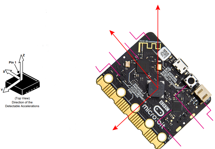
After referring to the MMA8653FC data manual and the hardware schematic diagram of the micro: bit main board, the accelerometer coordinate of the micro: bit is shown in the figure below:
7. Code Explanation