Project 4 Servo Motor
1.Introduction
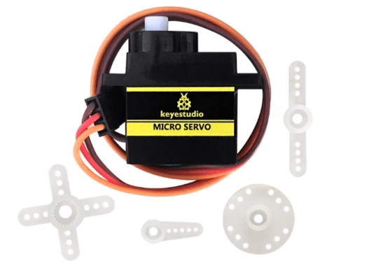
Servomotor is a position control rotary actuator. It mainly consists of housing, circuit board, core-less motor, gear and position sensor. The receiver or MCU outputs a signal to the servomotor. The motor has a built-in reference circuit that gives out reference signal, cycle of 20ms and width of 1.5ms. The motor compares the acquired DC bias voltage to the voltage of the potentiometer and outputs a voltage difference. The IC on the circuit board will decide the rotate direction accordingly and drive the core-less motor. The gear then passes the force to the shaft. The sensor will determine if it has reached the commanded position according to the feedback signal.
Servomotors are used in control systems that require to have and maintain different angles.When the motor speed is definite, the gear will cause the potentiometer to rotate. When the voltage difference reduces to zero, the motor stops. Normally, the rotation angle range is among 0-180 degrees.
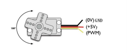
Servomotor comes with many specifications. But all of them have three connection wires, distinguished by brown, red, orange color(different brand may have different color). Brown one is for GND, red one for power positive, orange one for signal Line.
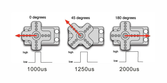
The rotating angle of the servo motor is controlled by regulating the duty cycle of the PWM(Pulse-Width Modulation) signal. The standard cycle of the PWM signal is 20ms(50Hz). Theoretically, the width is distributed between 1ms-2ms, but in fact, it’s between 0.5ms-2.5ms. The width corresponds the rotate angle from 0° to 180°. But note that for different brand motor, the same signal may have different rotating angle.
Mastering some basic knowledge, let’s learn how to control a servomotor. In this experiment, you only need a servomotor and several jumper wires.
2.Connection & Sample Program
There are two ways to control a servomotor with Arduino. One is to use a common digital sensor port of Arduino to produce square wave with different duty cycle to simulate PWM signal and then use that signal to control the positioning of the motor. Another way is to directly use the Servo function of the Arduino to control the motor. In this way, the program will be more easier but it can only control two-contact motor because of the servo function, only digital pin 9 and 10 can be used. The Arduino drive capacity is limited. So if you need to control more than one motor, you will need external power.
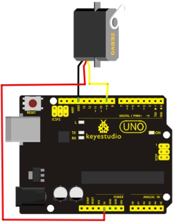
3.Connection Diagram
4.Sample Code
int servopin=9;// select digital pin 9 for servomotor signal line
int myangle;// initialize angle variable
int pulsewidth;// initialize width variable
int val;

void servopulse(int servopin,int myangle)// define a servo pulse function
{
    pulsewidth=(myangle*11)+500;// convert angle to 500-2480 pulse width
    digitalWrite(servopin,HIGH);// set the level of servo pin as “high”
    delayMicroseconds(pulsewidth);// delay microsecond of pulse width
    digitalWrite(servopin,LOW);// set the level of servo pin as “low”
    delay(20-pulsewidth/1000);
}

void setup()
{
    pinMode(servopin,OUTPUT);// set servo pin as “output”
    Serial.begin(9600);// connect to serial port, set baud rate at “9600”
    Serial.println("servo=o_seral_simple ready" ) ;
}

void loop()// convert number 0 to 9 to corresponding 0-180 degree angle, LED blinks corresponding number of time
{
    val=Serial.read();// read serial port value
    if(val>'0'&&val<='9')
    {
        val=val-'0';// convert characteristic quantity to numerical variable
        val=val*(180/9);// convert number to angle
        Serial.print("moving servo to ");
        Serial.print(val,DEC);
        Serial.println();
        for(int i=0;i<=50;i++) // giving the servo time to rotate to commanded position
        {
        	servopulse(servopin,val);// use the pulse function
        }
    }
}
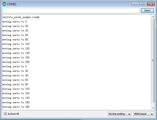
5.Result
When you input a number on serial monitor, the motor rotates to an angle which is equal to the number input, and the angle value will be displayed on screen, as shown in below figure.