Project 12 Servo
1. Description
This servo features high performance and high precision with a maximum rotation angle of 180°. Weighting only 9g, it is perfectly suitable for any mini device in multiple occasions. What’s more, it enjoys short startup time, low noise and strong stability.
2. Working Principle
Angle range: 180° (360°, 180° and 90°)
Drive voltage: 3.3V or 5V
Pin: Three wires
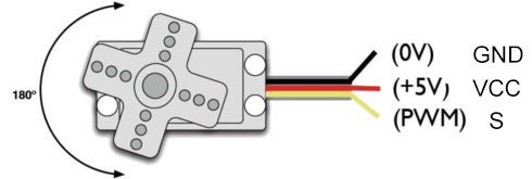
GND: Grounded(brown)
VCC: A red pin that connects to a +5v (3.3V) power
S: A orange signal pin that controlled via PWM signal
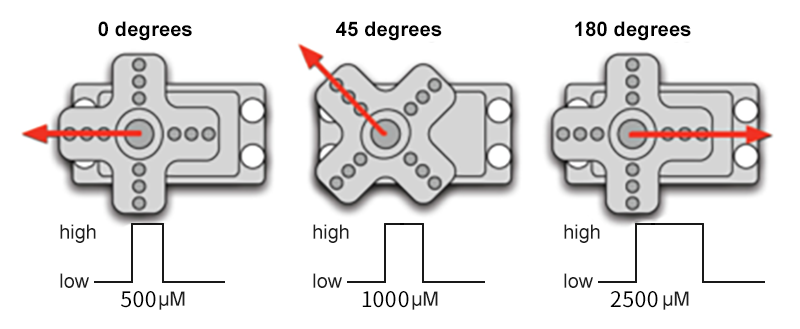
Control Principle: The rotation angle is controlled via duty cycle of PWM. Theoretically, standard PWM cycle is 20ms(50Hz), so pulse width should distribute within 1ms~2ms. However, the actual pulse width reaches 0.5ms~2.5ms, which corresponds to 0°~180°. Pay attention that, for the same signal, the rotation angle may vary from servo brands.
3. Wiring Diagram
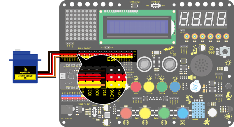
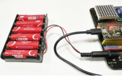
Add an external power source instead of just using USB for power.
4. Test Code
int servoPin = 4;//servo PIN

void setup()
{
  pinMode(servoPin, OUTPUT);//servo pin is set to output
}

void loop()
{
  for(int i = 0 ; i <= 180 ; i++)
  {
   servopulse(servoPin, i);//Set the servo to rotate from 0° to 180°
  delay(10);//delay 10ms
  }
  for(int i = 180 ; i >= 0 ; i--)
  {
   servopulse(servoPin, i);//Set the servo to rotate from 180° to 0°
  delay(10);//delay 10ms
  }
}

void servopulse(int pin, int myangle)
{ //Impulse function
  int pulsewidth = map(myangle, 0, 180, 500, 2500); //Map Angle to pulse width
  for (int i = 0; i < 10; i++)
  { //Output a few more pulses
    digitalWrite(pin, HIGH);//Set the servo interface level to high
    delayMicroseconds(pulsewidth);//The number of microseconds of delayed pulse width value
    digitalWrite(pin, LOW);//Lower the level of servo interface
  }
}
5. Test Result
After connecting the wiring and uploading code, the servo starts to rotate from 0° to 180° and then reverse.