Project 2 Breathing LED
1.Description
Arduino breathing led utilizes on-board programmable PWM to output analog waveform. After powering on, LED brightness can be adjusted through duty cycle of the waveform to eventually realize the effect of breathing led.
In this way, ambient light can be simulated by changing LED brightness over time. Also, breathing led can form a colorful mini light to construct a tranquil and warm environment.
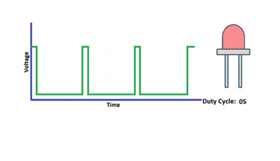
2. What is PWM?
PWM controls analog output via digital means, which is able to adjust duty cycle of the wave (a signal circularly shifting between high level and low level).
For Arduino, digital ports of voltage output are LOW and HIGH, which respectively correspond to 0V and 5V. Generally, we define LOW as 0 and HIGH as 1. Arduino will output 500 signals of 0 or 1 within 1s. If they are “1”, 5V will be output. Oppositely, if they are all 0, the output will be 0V. Or if they are 010101010101…, the average output will be 2.5V.
In other words, output ratio of 0 and 1 affects the voltage value, the more 0 and 1 signals are output per unit time, the more accurate the control will be.
The GPIO34, 35, 36, and 39 of ESP32 cannot use PWM.
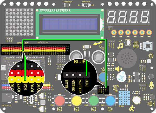
3. Wiring Diagram
4.Test Code
/*
  keyestudio ESP32 Inventor Learning Kit
  Project 2: Breathing LED
  http://www.keyestudio.com
*/
#define PIN_LED   5   //define the led pin
#define CHN       0   //define the pwm channel
#define FRQ       1000  //define the pwm frequency
#define PWM_BIT   8     //define the pwm precision

void setup()
{
  ledcSetup(CHN, FRQ, PWM_BIT); //setup pwm channel
  ledcAttachPin(PIN_LED, CHN);  //attach the led pin to pwm channel
}

void loop()
{
  for (int i = 0; i < 255; i++) //make light fade in
  {
    ledcWrite(CHN, i);
    delay(10);
  }
  for (int i = 255; i > -1; i--) //make light fade out
  {
    ledcWrite(CHN, i);
    delay(10);
  }
}
5.Test Result
After uploading the code, we will see the LED slowly brighten and dim, just like the rhythm of breathing.