Project 4 Traffic Light
1. Description
The traffic light module is a device used to control the route of pedestrians and vehicles. It includes a red, a yellow and a green light, which implies different instructions.
Red for Stop: Pedestrians and vehicles stop proceeding.
Yellow for Caution: Pedestrians and vehicles are ready for stopping. If the drive is already in process, the speed should be slow.
Green for Proceed: Pedestrians and vehicles keep going with the abidance of traffic regulations.
In this project, you can use Arduino to write code to control traffic lights. For instance, set the duration of each lights and the interval time among them. Besides, you may also add a timer to alter light colors to schedule.
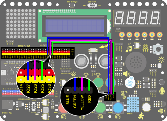
2. Wiring Diagram
3. Test Code
/*
  keyestudio ESP32 Inventor Learning Kit
  Project 4 Traffic Light
  http://www.keyestudio.com
*/
int greenPin = 27;   //Green LED connects to IO27
int yellowPin = 26; //Yellow LED connects to IO26
int redPin = 25;   //Red LED connects to IO25

void setup()
{
  //Set all LED interfaces to output mode
  pinMode(greenPin, OUTPUT);
  pinMode(yellowPin, OUTPUT);
  pinMode(redPin, OUTPUT);
}

void loop()
{
  digitalWrite(greenPin, HIGH); //Light green LED up
  delay(5000);  //Delay 5s
  digitalWrite(greenPin, LOW); //Turn green LED off
  for (int i = 1; i <= 3; i++) //Execute for 3 times
  {
    digitalWrite(yellowPin, HIGH); //Light yellow LED up
    delay(500); //Delay 0.5s
    digitalWrite(yellowPin, LOW); // Turn yellow LED off
    delay(500); //Delay 0.5s
  }
  digitalWrite(redPin, HIGH); //Light red LED up
  delay(5000);  //Delay 5s
  digitalWrite(redPin, LOW); //Turn red LED off

}
4. Test Result
After uploading the code, green LED will light up for 5s, yellow LED will blink for 3 times, and red LED will light up for 5s, in circulation.