Project 5 Control electricity
1.Introduction
In this lesson, we will learn to use a very important element in the switch family. It’s called relay. Relay is specially used in controlling a high-power circuit by a low-power signal. Here, we will only do a simple module test due to limited resources while you can expend the circuit and the program to have more fun with it.
2.Hardware required
EASY plug controller Board x1
USB cable x1
EASY plug cable x1
EASY plug Single Relay Module x1
Next is a brief introduction of this relay module.
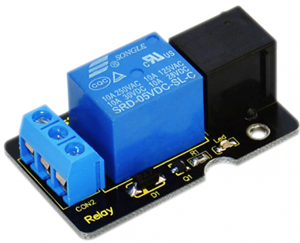
Relay is an automatic switch element with isolation function. It’s widely used in remote control, remote sensing, communication, automatic control, mechatronics and electronic devices. It is one of the most important control elements. Besides, it’s easy to control and use just by inputting different level signals to corresponding ports of the relay. The single relay we introduced here has a status indicator light, convenient for you to observe the on and off status of the relay. Below are its specifications:
Type: Digital
Rated current: 10A (NO) 5A (NC)
Maximum switching voltage: 150VAC 24VDC
Digital interface
Control signal: TTL level
Rated load: 8A 150VAC (NO) 10A 24VDC (NO), 5A 250VAC (NO/NC) 5A 24VDC (NO/NC)
Maximum switching power: AC1200VA DC240W (NO) AC625VA DC120W (NC)
Contact action time: 10ms
Size: 46.5*28mm
Weight: 15g
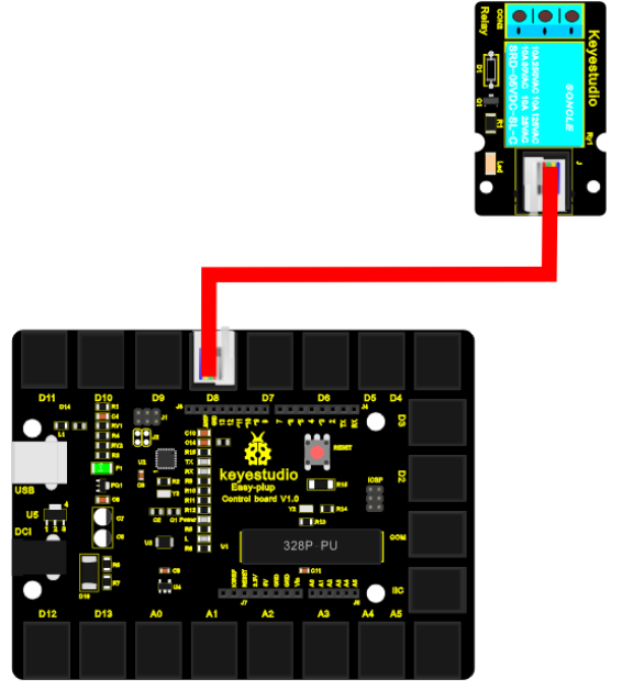
3.Connection Diagram
Now, connect the module to the IIC port of the controller board using the EASY plug cable.Now, let’s connect this module to the D8 port of the controller board using the EASY plug cable.
4.Sample Code
Connect the board to your PC using the USB cable; copy below code into Arduino IDE, and click upload to upload it to your board.
int Relay = 8;
void setup()
{
  pinMode(Relay, OUTPUT);     //Set Pin3 as output
}

void loop()
{
  digitalWrite(Relay, HIGH);   //Turn on relay
  delay(1000);
  digitalWrite(Relay, LOW);   //Turn on relay
  delay(1000);
}
5.Result
After all the above are done, you can hear the relay module is ticking, and the LED on the module is being on for 1S (“ON” contacts are connected), and off for 1S (“ON” contacts are connected).