Project 9 It’s moving
1.Introduction
In this lesson, we will learn how to measure the static acceleration of an object in its X, Y and Z direction using an ADXL345 three axis acceleration module. This module is also suitable for measuring dynamic acceleration.
2.Hardware required
EASY plug controller Board x1
USB cable x1
EASY plug cable x1
EASY plug ADXL345 Three Axis Acceleration Module x1
Below is a brief introduction of this module.
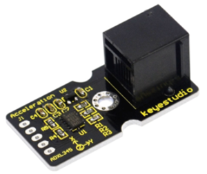
The ADXL345 module is a 3-axis MEMS accelerometer with low power consumption and compact design. It’s of high resolution of 13-bit, measurement up to ±16g(gravitational force). Digital output data is formatted as 16-bit twos complement and is accessible through either a SPI (3- or 4-wire) or I2C digital interface. Below are its specifications:
2.0-3.6VDC Supply Voltage
Ultra Low Power: 40uA in measurement mode, 0.1uA in standby@ 2.5V
Tap/Double Tap Detection
Free-Fall Detection
SPI and I2C interfaces
Size: 40*20mm
Weight: 3g
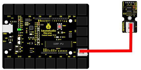
3.Connection Diagram
Now, let’s connect this module to the IIC port of the controller board using the EASY plug cable.
4.Sample Code
Connect the board to your PC using the USB cable; copy below code into Arduino IDE, and click upload to upload it to your board.
#include <Wire.h>    // place file “Wire.h” under the directory “libraries” of Arduino
// Registers for ADXL345
#define ADXL345_ADDRESS (0xA6 >> 1)  // address for device is 8 bit but shift to the
                                     // right by 1 bit to make it 7 bit because the
                                     // wire library only takes in 7 bit addresses
#define ADXL345_REGISTER_XLSB (0x32)

int accelerometer_data[3];
// void because this only tells the cip to send data to its output register
// writes data to the slave's buffer
void i2c_write(int address, byte reg, byte data)
{
  // Send output register address
  Wire.beginTransmission(address);
  // Connect to device
  Wire.write(reg);
  // Send data
  Wire.write(data); //low byte
  Wire.endTransmission();
}

// void because using pointers
// microcontroller reads data from the sensor's input register
void i2c_read(int address, byte reg, int count, byte* data) {
  // Used to read the number of data received
  int i = 0;
  // Send input register address
  Wire.beginTransmission(address);
  // Connect to device
  Wire.write(reg);
  Wire.endTransmission();

  // Connect to device
  Wire.beginTransmission(address);
  // Request data from slave
  // Count stands for number of bytes to request
  Wire.requestFrom(address, count);
  while(Wire.available()) // slave may send less than requested
  {
    char c = Wire.read(); // receive a byte as character
    data[i] = c;
    i++;
  }
  Wire.endTransmission();
}

void init_adxl345()
{
  byte data = 0;

  i2c_write(ADXL345_ADDRESS, 0x31, 0x0B);   // 13-bit mode  +_ 16g
  i2c_write(ADXL345_ADDRESS, 0x2D, 0x08);   // Power register

  i2c_write(ADXL345_ADDRESS, 0x1E, 0x00);   // x
  i2c_write(ADXL345_ADDRESS, 0x1F, 0x00);   // Y
  i2c_write(ADXL345_ADDRESS, 0x20, 0x05);   // Z

  // Check to see if it worked!
  i2c_read(ADXL345_ADDRESS, 0X00, 1, &data);
  if(data==0xE5)
    Serial.println("it work Success");
  else
    Serial.println("it work Fail");
}

void read_adxl345()
{
  byte bytes[6];
  memset(bytes,0,6);

  // Read 6 bytes from the ADXL345
  i2c_read(ADXL345_ADDRESS, ADXL345_REGISTER_XLSB, 6, bytes);
  // Unpack data
  for (int i=0;i<3;++i) {
    accelerometer_data[i] = (int)bytes[2*i] + (((int)bytes[2*i + 1]) << 8);
  }
}

// initialise and start everything
void setup()
{
  Wire.begin();
  Serial.begin(9600);
  for(int i=0; i<3; ++i)
  {
    accelerometer_data[i]  = 0;
  }
  init_adxl345();
}

void loop()
{
  read_adxl345();
  Serial.print("ACCEL: ");
  Serial.print(float(accelerometer_data[0])*3.9/1000);//3.9mg/LSB scale factor in 13-bit mode
  Serial.print("\t");
  Serial.print(float(accelerometer_data[1])*3.9/1000);
  Serial.print("\t");
  Serial.print(float(accelerometer_data[2])*3.9/1000);
  Serial.print("\n");
  delay(100);
}
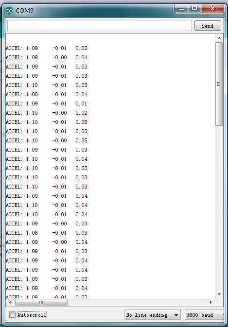
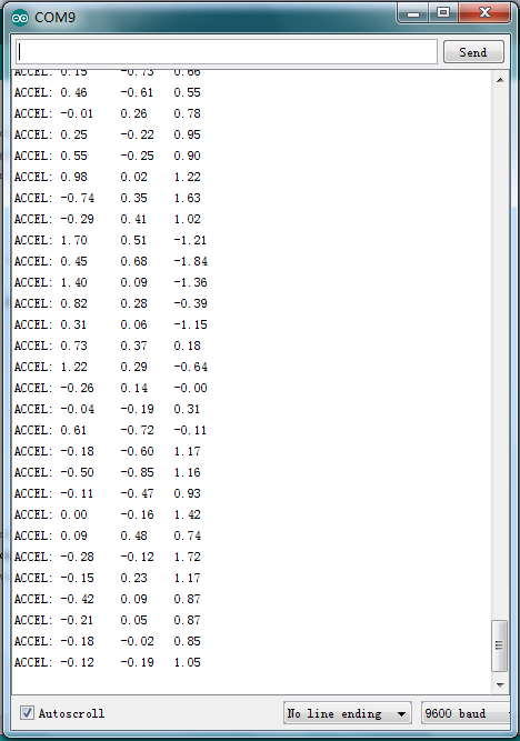
5.Result
Now, open serial monitor, you can see it displays data as pic 1; when you move the module towards different direction, you can see the data changes as pic 2.