Project 16 Traffic Light
1.Overview
When walking at the crossroad, you can see the traffic light command the orderly movement of pedestrians and vehicles. So how is the traffic light controlled to operate? In this project, we will connect a traffic light module to our sensor shield, controlling traffic light blink with micro:bit. You will learn how to simulate the running of traffic light.
2.Components Required
Micro:bit Main Board *1
Keyestudio micro bit honeycomb Traffic Light Module*1
Micro:bi USB Cable *1
Alligator Clip Cable*4
3.Component Introduction
About Traffic Light Module:
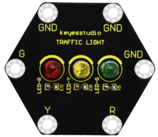
The keyestudio micro bit Honeycomb traffic light module is fully compatible with the micro bit control board. In the experiment, we connect this module to the micro:bit control board using crocodile clip wires. There are 6 ports on the module, including 3 GND ports which are connected. The module comes with 3 LED lights in red, yellow and green. We can control the 3 LEDs on and off on the module , and simulate the roadside traffic lights flashing.
4.Technical parameters
Working voltage: DC 3.0-3.3V
Control port: digital port
Size: 42mm*47mm*12mm
Weight: 5.7g
Environmental attributes: ROHS
5.Connection Diagram
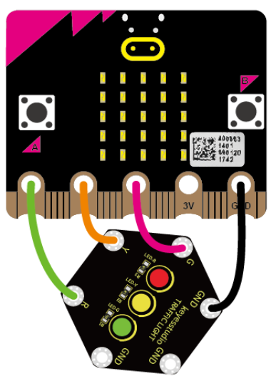
Connect the keyestudio Traffic Light Module to micro:bit main board with 4 alligator clip cables. Ring R to P0, Y to P1, G to P2 and GND to GND. Connect the micro:bit to your computer with a micro USB cable.
6.Coding
So now let’s move to coding. Below are some steps to follow.
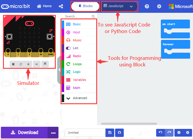
Open the https://makecode.micro:bit.org/#editor to write your code.
Microsoft MakeCode is actually a platform that allows us to code for a micro:bit, and also provides an interactive simulator where we can debug and run our code, and will be able to see what to expect out right there on the site.
Go to MakeCode and choose My Projects and click on New Projects.
If you want to see the codes behind, then you can click on JavaScript and it will display JavaScript code there in IDE.
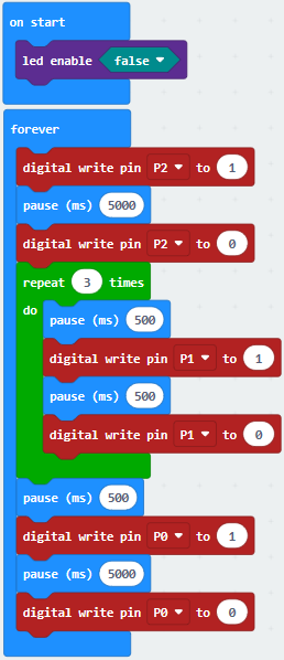
7.The following test code is for your reference
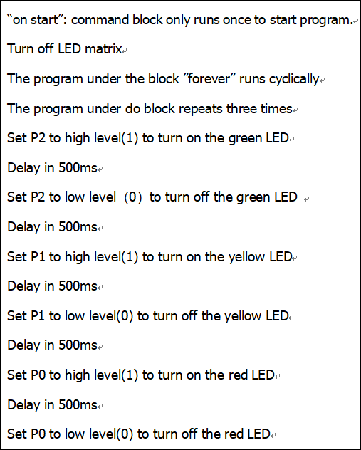
8.Test Results
When wiring the main board up and powering it up and uploading the test code to it, you will find the green LED on it lights up at 5s and then turns off, followed by the yellow LED which flashes three times at 0.5s and then the red LED is on at 5s. Repeat the sequence.