Project 25 Hear Footsteps
1.Overview
As for those corridor lights, when we walk through the corridor to make a sound, the corridor light will automatically light up, after that, quiet down, the lights are off. Why? Actually inside the lighting circuit, it has installed a sound sensor. When detects the sound, light is turned on, or else LED off.
In this lesson, we connect an analog sound sensor to P0 of micro:bit, then detect the outside sound via reading the analog value of P0.The greater the external sound, the greater the analog value.You can see the analog value is displayed on the micro:bit LED matrix, or check it from serial monitor of CoolTerm software.
2.Components Required
Micro:bit Main Board*1
Keyestudio Edge Connector IO Breakout Board for Micro:bit*1
USB Cable*1
keyestudio Analog Sound Sensor*1
keyestudio Digital Red LED Module*1
Alligator Clip Wire*6
3.Component Introduction
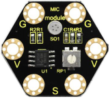
About Keyestudio micro bit honeycomb microphone module :
This keyestudio microphone module is fully compatible with micro:bit control board. When using, connect the module to micro:bit control board using Crocodile clip line.It is a sound detection device, an analog signal output device.It is mainly composed of a MIC head, a LM358D chip and a potentiometer.
When the microphone detects sound, and converts it into a voltage signal; then amplifies it through the LM358D chip. The potentiometer is used to adjust the signal amplification.
There are total 6 rings on the module. Note that two G rings, two V rings and two S rings are separately connected. G for ground; V for 3V; S for signal pin(0 1 2).We can work out the sound volume by reading the analog value of signal end.
4.Technical Parameters
Working voltage: DC 3.0-3.3V
Output signal: Analog signal
Dimensions: 31mm*27mm*4mm
Weight: 2g
Environmental attributes: ROHS
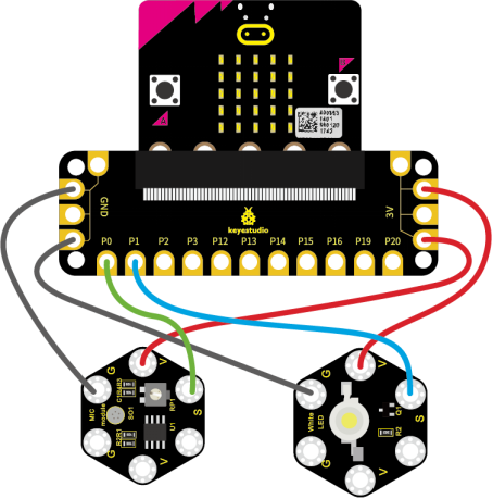
5.Connection Diagram
Attach the main board to Keyestudio Edge Connector IO Breakout Board for Micro:bit;
Connect the keyestudio micro bit honeycomb sound sensor to the shield with 3 Alligator clip cables;
Ring S to P0, V to 3V, and G to GND.
Connect the keyestudio micro bit 1W LED module to the shield with 3 Alligator clip cables.
Ring S to P1, V to 3V, and G to GND.
Interface the micro:bit to your computer with a micro USB cable.
6.Coding
So now let’s move to coding. Below are some steps to follow.
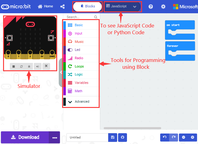
Open the https://makecode.micro:bit.org/#editor to write your code.
Microsoft MakeCode is actually a platform that allows us to code for a micro:bit, and also provides an interactive simulator where we can debug and run our code, and will be able to see what to expect out right there on the site.
Go to MakeCode and choose My Projects and click on New Projects.
If you want to see the codes behind, then you can click on JavaScript and it will display JavaScript code there in IDE.
7.The following test code is for your reference
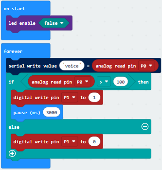
8.Test Results
Wire according to connection diagram and upload the test code to the main board.
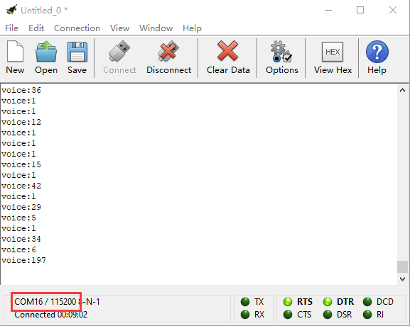
Open CoolTerm →click Options →click SerialPort to set COM port and baud rate (set it to 115200)→click OK→click Connect.
When ambient sound changes, these changes will be shown on the CoolTerm serial port monitor, as shown below. The louder the sound, the bigger the analog value. When the analog value of sound is bigger than 100, the LED lights up; when the value is smaller than 100, the LED remains off.