Project 4 Programmable Buttons
1.Project Description
Buttons can be used to control circuits. In an integrated circuit with a button, the circuit is connected when pressing the button and it is open the other way around.
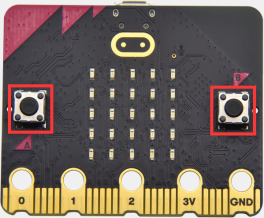
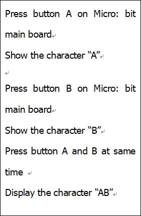
Micro: Bit main board V2 boasts three buttons, two are programmable buttons(marked with A and B), and the one on the other side is a reset button. By pressing the two programmable buttons can input three different signals. We can press button A or B alone or press them together and the LED dot matrix shows A,B and AB respectively. Let’s get tarted.
2.Components Needed
Micro:bit main board V2 *1
Micro USB cable*1
3.Test Code 1
Link computer with micro:bit board by micro USB cable, and program in MakeCode editor.
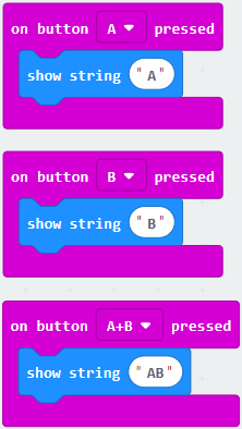
(1)Delete“on start”and“forever”firstly,then click“Input”→“on button A pressed”.
(2)A. Click“Basic”→“show string”;
B. Then place it into“on button A pressed”block, change “Hello!”into“A”.

(2)Copy code string once, tap the drop-down button“A”to select“B”and modify,character“A”into“B”.
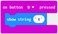
(3)Copy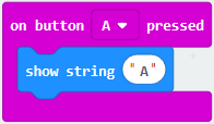 once,and set to“on button A+B pressed”and“show string “AB”
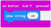 .
.
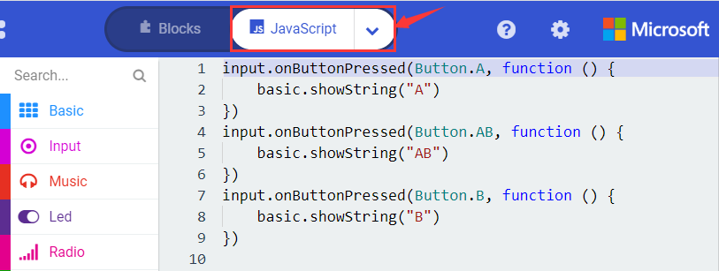
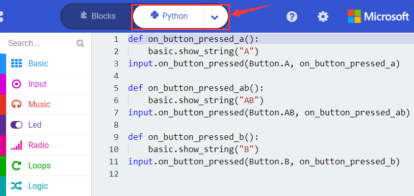
Complete Code:
Select “JavaScript” and“Python”to switch into JavaScript and Python language code:
4.Test Results 1
After uploading test code 1 to micro:bit main board V2 and powering the main board via the USB cable, the 5*5 LED dot matrix shows A if button A is pressed, B if button B pressed, and AB if button A and B pressed together.
5.Test Code 2
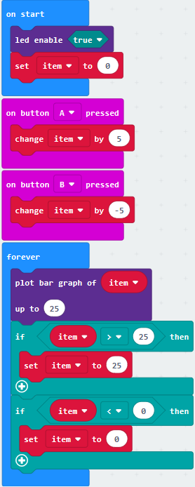
(1) A. Click“Led”→“more”→“led enable false”.
B. Put it into the block“on start”,click drop-down triangle button to select“true”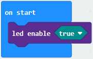 .
.
(2) A. Tap“Variables”→“Make a Variable…”→“New variable name:”
B. Enter“item”in the dialog box and click“OK”,then variable“item”is produced. And move“set item to 0”into“on start”block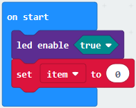 .
.
(3)A. Click“Input”→“on button A pressed”.
B. Go to“Variables”→“ change item by 1 ”.
C. Place it into“on button A pressed”and 1 is modified into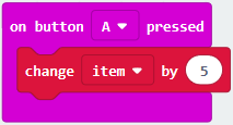 .
.
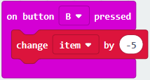
(4) Duplicate code string once, click the drop-down button to select“B”,then set“change item by -5”.
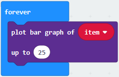
(5)A. Enter“Led”→“plot bar graph of 0 up to 0”.
B. Keep it into“forever”block.
C. Go to“Variables”to move“item”into 0 box,change 0 into 25.
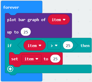
(6) A. Go to“Logic”to move out “if…true…then…”and “=”blocks.
B. Keep“=”into“true”box and set to “>”.
C. Select“item”in the “Variables” and lay it down at left box of “>”,change 0 into 25;
D. Enter“Variables”to drag“set item to 0”block into“if…true…then…”, alter 0 into 25.
(7)A. Replicate code string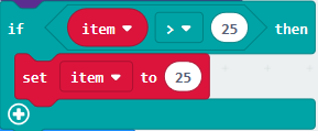 once .
B. “>” is modified into “<” and 25 is changed into 0.
C. Leave it beneath code string.
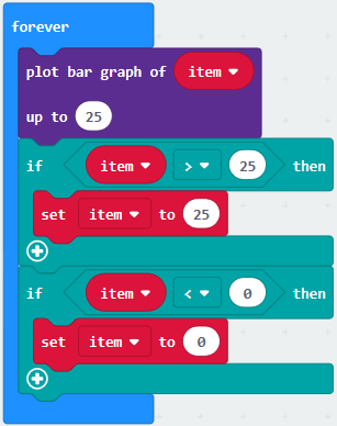
Complete Program:
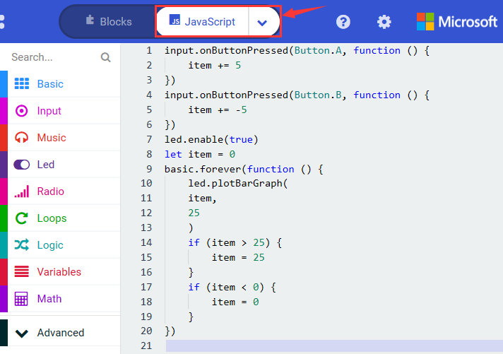
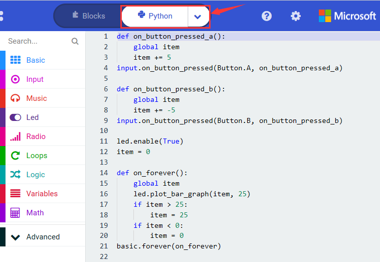
Select “JavaScript” and“Python”to switch into JavaScript and Python language code:
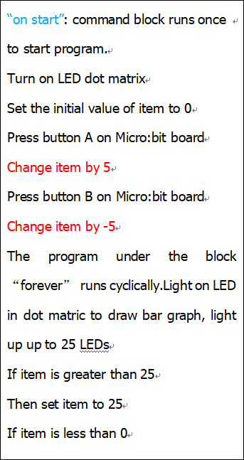
6.Test Results 2
After uploading test code 2 to micro:bit main board V2 and powering the main board via the USB cable, when pressing the button A the LEDs turning red increase while when pressing the button B the LEDs turning red reduce.