Project 19 Use Button to Control LED
1.Overview
When design the circuit, button switch is a commonly used component. The micro:bit main board has three built-in buttons, however, sometimes still need to use external button when design the circuit. So in this project, you will learn how to use our push button module to control the LEDs on Keyestudio micro bit honeycomb digital LED module.
2.Component Required
Micro:bit Main Board*1
Keyestudio Edge Connector IO Breakout Board for Micro:bit*1
USB Cable*1
keyestudio Digital Push Button*1
keyestudio Digital White LED Module*1
Alligator Clip Wires*6
3.Components Introduction
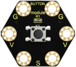
About Keyestudio micro bit honeycomb tactile button module:
This keyestudio tactile button module is fully compatible with micro:bit control board. It mainly uses a button element, which is a digital signal output device.
When using, connect the module to micro:bit control board using Crocodile clip line.
There are total 6 rings on the module. Note that two G rings, two V rings and two S rings are connected. G for ground; V for 3V; S for signal pin(0 1 2).
When press the button, the signal end of micro:bit main board will input HIGH level signal.
4.Technical Parameters
Working voltage: DC 3.0-3.3V
Output Signal: Digital
Dimensions: 31mm*27mm*6.5mm
Weight: 1.8g
Environmental attributes: ROHS
5.About Keyestudio Edge Connector IO Breakout Board for
Micro:bit
The BBC micro:bit is a powerful handheld, fully programmable, computer designed by the BBC. It was designed to encourage children to get actively involved in technical activities, like coding and electronics. It supports the PXT graphical programming interface developed by Microsoft and can be used under Windows, MacOS, iOS, Android and many other operating systems without downloading additional compiler.
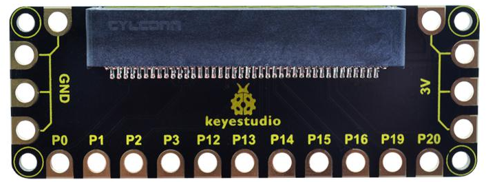
This breakout board has been designed to offer an easy way to connect additional circuits and hardware to the edge connector on the BBC micro:bit. It provides an easy way of connecting circuits using Alligator clip lines.
This edge connector offers access to a number of the BBC micro:bit processor pins, such as power IO (input/output) interface, connection pins P0、P1、P2、P3、P12、P13、P14、P15、P16、P19、P20 .
There are 2 kinds of power supply for the breakout board and micro:bit main board.
Direct to connect the battery case carried with batteries to micro:bit main board for powering;
Connect the golden rings 3V GND with alligator clip lines for power supply;
The breakout board also comes with 4 fixed holes at the edge, easy to mount on any other devices.
Technical Parameters:
Operating voltage: DC3.0-3.3V
Dimensions: 89mm*33mm*12mm
Weight:14.8g
6.Connection Diagram
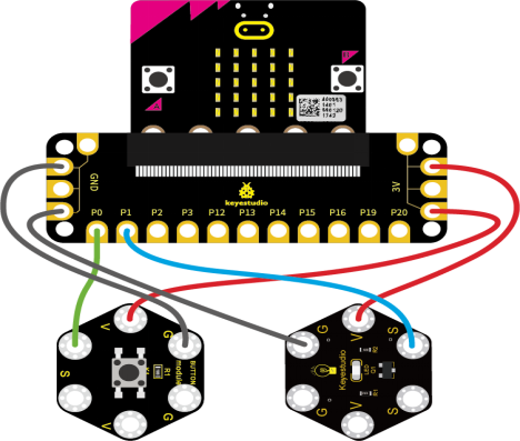
Attach the main board to Keyestudio Edge Connector IO Breakout Board for Micro:bit;
Connect the keyestudio micro bit honeycomb tactile button module to the shield with 3 Alligator clip cables;
Ring S to P0, V to 3V, and G to GND.
Connect the keyestudio micro bit digital LED module to the shield with 3 Alligator clip cables.
Ring S to P1, V to 3V, and G to GND.
Interface the micro:bit to your computer with a micro USB cable.
7.Coding
So now let’s move to coding. Below are some steps to follow.
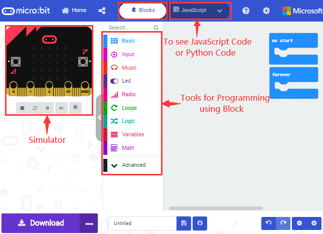
Open the https://makecode.micro:bit.org/#editor to write your code.
Microsoft MakeCode is actually a platform that allows us to code for a micro:bit, and also provides an interactive simulator where we can debug and run our code, and will be able to see what to expect out right there on the site.
Go to MakeCode and choose My Projects and click on New Projects.
If you want to see the code behind, then you can click on JavaScript and it will display JavaScript code there in IDE.
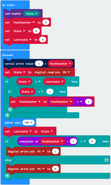
8.The following test code is for your reference
9.Test Results
Wire according to connection diagram and upload the test code to the main board;
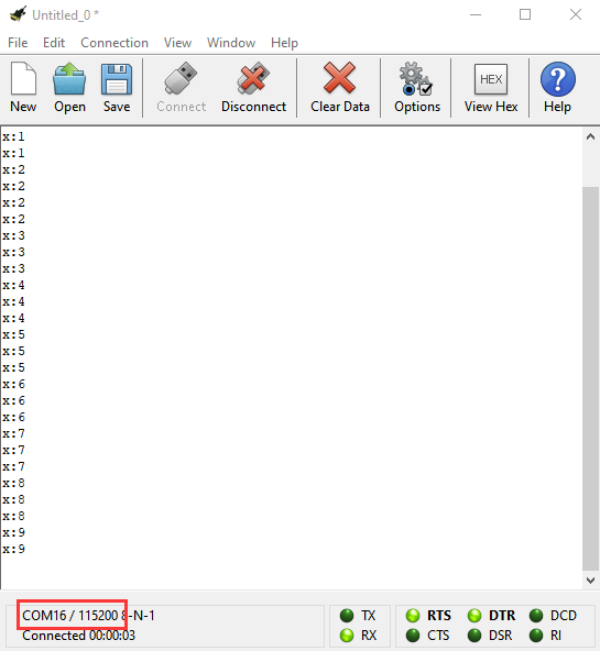
Open CoolTerm →click Options →click SerialPort to set COM port and baud rate (set it to 115200)→click OK→click Connect;
When the button is pressed continuously, the CoolTerm serial port monitor displays a number gradually increasing by 1, as shown in the figure below. At the same time, press the button, the LED lights up; then press it again, the LED goes out.