Project 24 Light Brightness
1.Overview
It is seen that sensors are everywhere in our daily life. Some public street lights automatically light up during the day and automatically go out at night. Why?In fact, those lights make use of a photosensitive element that can measure the brightness of external light.In the evening, when outside brightness becomes lower, the street light is automatically controlled to be turned on.
In this project, you will learn how to use our keyestudio photocell sensor and micro:bit to control the brightness of external light. Show the result on 5*5 LED of micro:bit or serial monitor of CoolTerm software
2.Components Required
Micro:bit Main Board*1
Keyestudio Edge Connector IO Breakout Board for Micro:bit*1
USB Cable*1
keyestudio Photoresistor Sensor*1
keyestudio Digital Red LED Module*1
Alligator Clip Wire*6
3.Component Introduction
About keyestudio micro bit honeycomb photoresistor :
The Keyestudio micro bit honeycomb photoresistor is fully compatible with micro bit control boards. In the experiment, we connect it with the micro: bit by a crocodile clip. There are 6 connectors which are G, G, V, V, S and S
Additionally, G is GND, V is VCC, and S is the signal end of the module.
The sensor also includes a photoresistor whose resistance varies with ambient lightness. The brighter the ambient environment is, the higher the resistance is. Otherwise, the lower the resistance is. During the test, we test the analog value of S end via a micro: bit board. The brighter the ambient environment is, the larger the analog value becomes; and the darker the light is, the smaller the analog value is.
4.Technical Parameters
Working voltage: DC 3.0-5V
Working current: 60mA
Maximum power: 300mW
Working temperature: -25 ℃ ~-65 ℃
Dimension: 30mm * 27mm * 5mm
Weight: 2.0g
Environmental attributes: ROHS
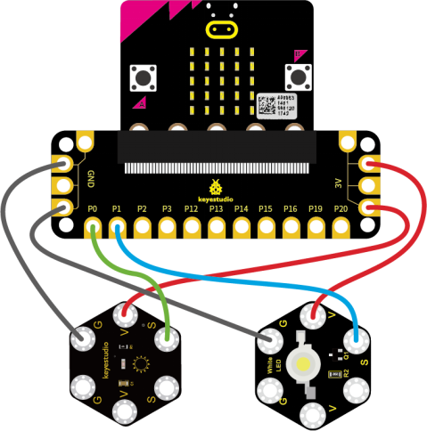
5.Connection Diagram
Attach the main board to Keyestudio Edge Connector IO Breakout Board for Micro:bit;
Connect the keyestudio micro bit honeycomb PIR motion module to the shield with 3 Alligator clip cables;
Ring S to P0, V to 3V, and G to GND.
Connect the keyestudio micro bit passive buzzer to the shield with 3 Alligator clip cables.
Ring S to P1, V to 3V, and G to GND.
Interface the micro:bit to your computer with a micro USB cable.
5.Coding
So now let’s move to coding. Below are some steps to follow.
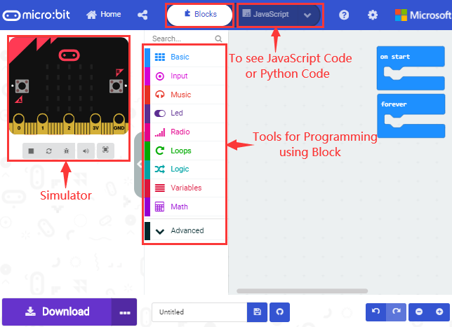
Open the https://makecode.micro:bit.org/#editor to write your code.
Microsoft MakeCode is actually a platform that allows us to code for a micro:bit, and also provides an interactive simulator where we can debug and run our code, and will be able to see what to expect out right there on the site.
Go to MakeCode and choose My Projects and click on New Projects.
If you want to see the codes behind, then you can click on JavaScript and it will display JavaScript code there in IDE.
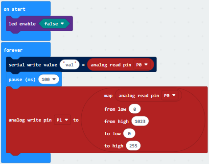
6.The following test code is for your reference
7.Test Results
Connect micro:bit to computer via USB cable and transfer code to micro:bit.
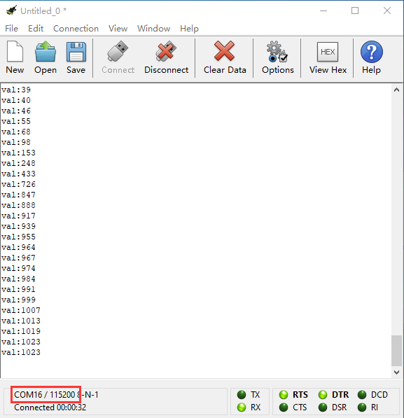
Open CoolTerm, click Options and select SerialPort, set COM port and baud rate(115200). Click OK and Connect.
CoolTerm monitor shows the corresponding analog signal, with the light intensity getting weaker, the analog value plummets gradually and red LED gets dimmer, otherwise, the analog value grows and red becomes brighter.