Project 31 Use Button to Control Buzzer and RGB
1.Overview
In the above project, we have introduced the tactile button module, the passive buzzer module and the RGB module.Now, we combine these sensor modules to create an interactive project. In this project, you will learn to play different tones and emit different colors of light using the tactile button module.
2.Components Required
Micro:bit Main Board*1
Keyestudio Edge Connector IO Breakout Board for Micro:bit*1
USB Cable*1
keyestudio Passive Buzzer Module*1
keyestudio Tactile Button Module*1
keyestudio 5050RGB Module*1
Alligator Clip Wire*10
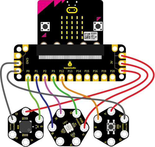
3.Connection Diagram
Attach the main board to Keyestudio Edge Connector IO Breakout Board for Micro:bit;
Connect the keyestudio micro bit honeycomb passive buzzer module to the shield with 3 Alligator clip cables;
Ring S to P0, V to 3V, and G to GND.
For tactile button module,ring S to P2, V to 3V, and G to GND.
For RGB module,ring B to P1, R to P2, G to P3 and V to 3V.
So now let’s move to coding. Below are some steps to follow.
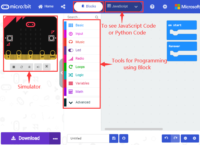
Open the https://makecode.micro:bit.org/#editor to write your code.
Microsoft MakeCode is actually a platform that allows us to code for a micro:bit, and also provides an interactive simulator where we can debug and run our code, and will be able to see what to expect out right there on the site.
Go to MakeCode and choose My Projects and click on New Projects.
If you want to see the codes behind, then you can click on JavaScript and it will display JavaScript code there in IDE.
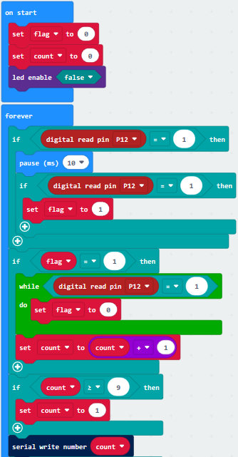
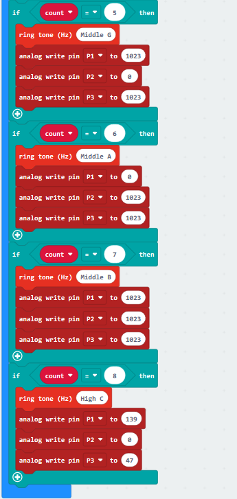
4.The following test code is for your reference

5.Test Results
Wire according to connection diagram and upload the test code to the main board.
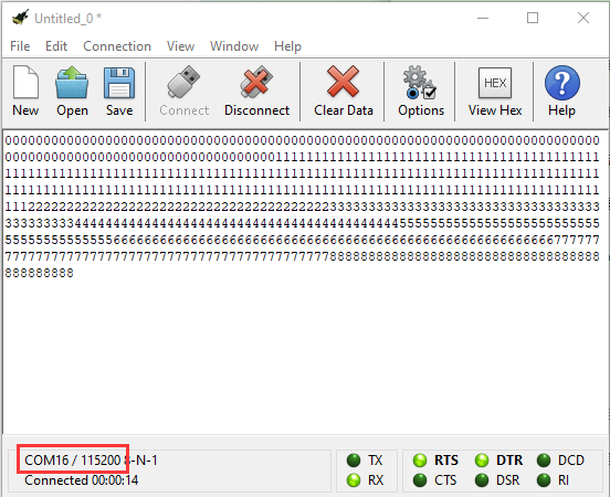
Open CoolTerm →click Options →click SerialPort to set COM port and baud rate (set it to 115200)→click OK→click Connect.
Touch the tactile button, the passive buzzer makes corresponding tone, the RGB sensor emits corresponding color and the Cool Term shows the number.